Chapter 4 Technical Information
CLV61x bar code scanner
42 © SICK AG · Germany · All rights reserved · Subject to change without notice 8015592/ZNI9/2017-06-13
Electrical installation
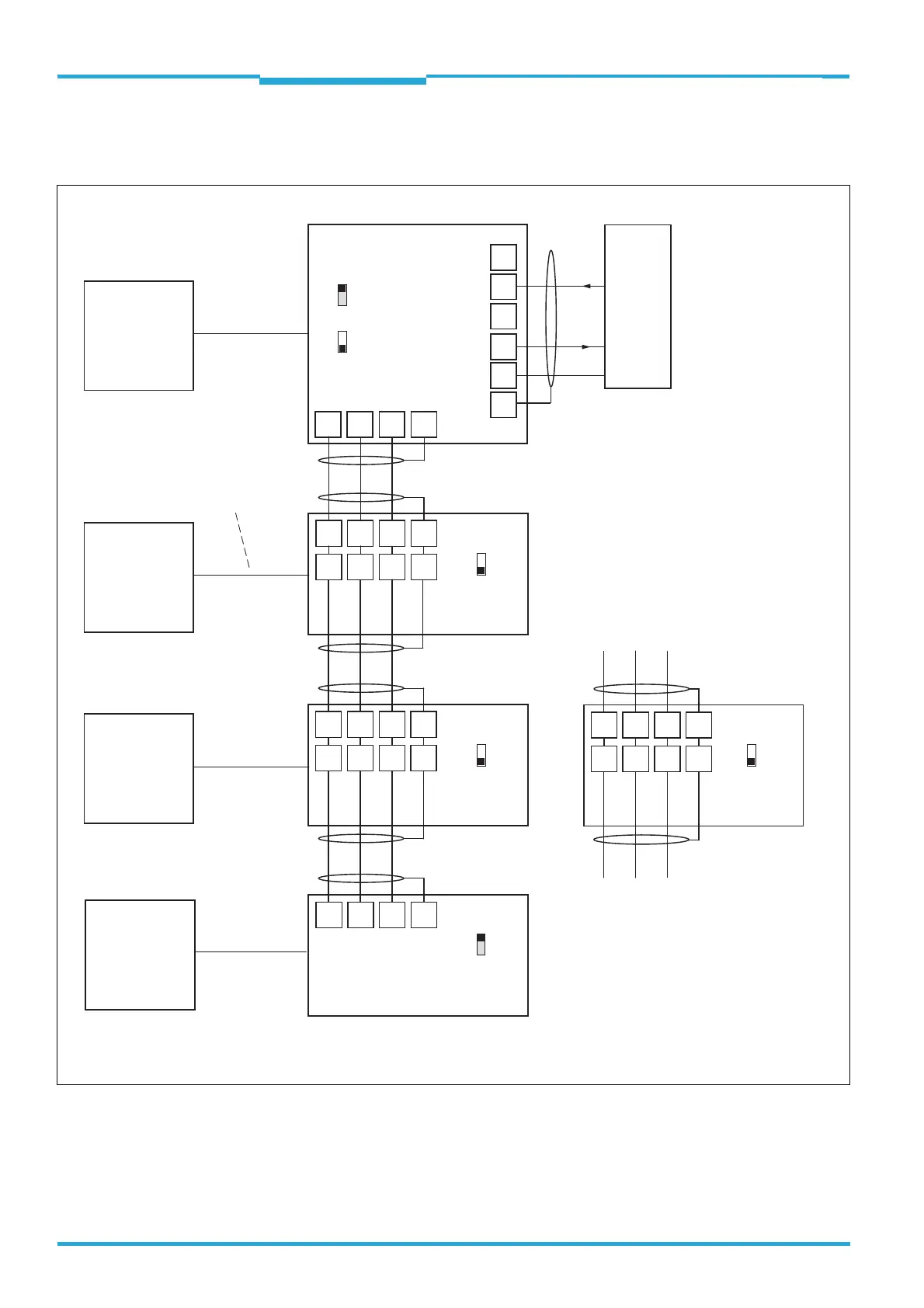
4.8.4 Wiring the CAN Data Interface in the CDM420-0001 Connection module
(CLV61x CAN and FIELDBUS series)
amongst
others
CAN
amongst
others
CAN
amongst
others
CAN
amongst
others
CAN
Shield
30 31 32 6
24
25
34
35
7
40 41 42 7
CDM420
CDM420
CDM420
(Slave)
(Slave)
(Slave)
GN = 01
(Master)
GN = 63
GN = 02
GN = 03
(max. 32 participants)
Stub
Switch
ON
OFF
S4 (TermCAN):
Switch
ON
OFF
S4 (TermCAN):
Switch
ON
OFF
S4 (TermCAN):
21 22 23 6
21 22 23 6
31 32 33 7
21 22 23 6
21 22 23 6
31 32 33 7
CDB620
Switch
ON
OFF
S2 (TermCAN):
CAN_H
CAN_L
Shield
GND
CAN_H
CAN_L
Shield
GND
CAN_H
CAN_L
Shield
GND
CAN_H
CAN_L
Shield
GND
CAN_H
CAN_L
Shield
GND
GND
Host
GND
RxD
TxD
RS-232
T‒/TxD
R‒/RxD
T+
R+
CDM420
26
CAN
CAN
CAN
Switch
ON
OFF
S4 (TermCAN):
Serial Host interface
Alternative connection module:
ON
OFF
S2 (RS485):
Connection of power supplies as well
as of reading clock sensor e.g. to the
master here not shown.
CLV61x CAN
CLV61x FIELDBUS
CLV61x CAN
CLV61x FIELDBUS
CLV61x CAN
CLV61x FIELDBUS
CLV61x CAN
CLV61x FIELDBUS
GN = Device number

 Loading...


