6
1
10
5
11
15
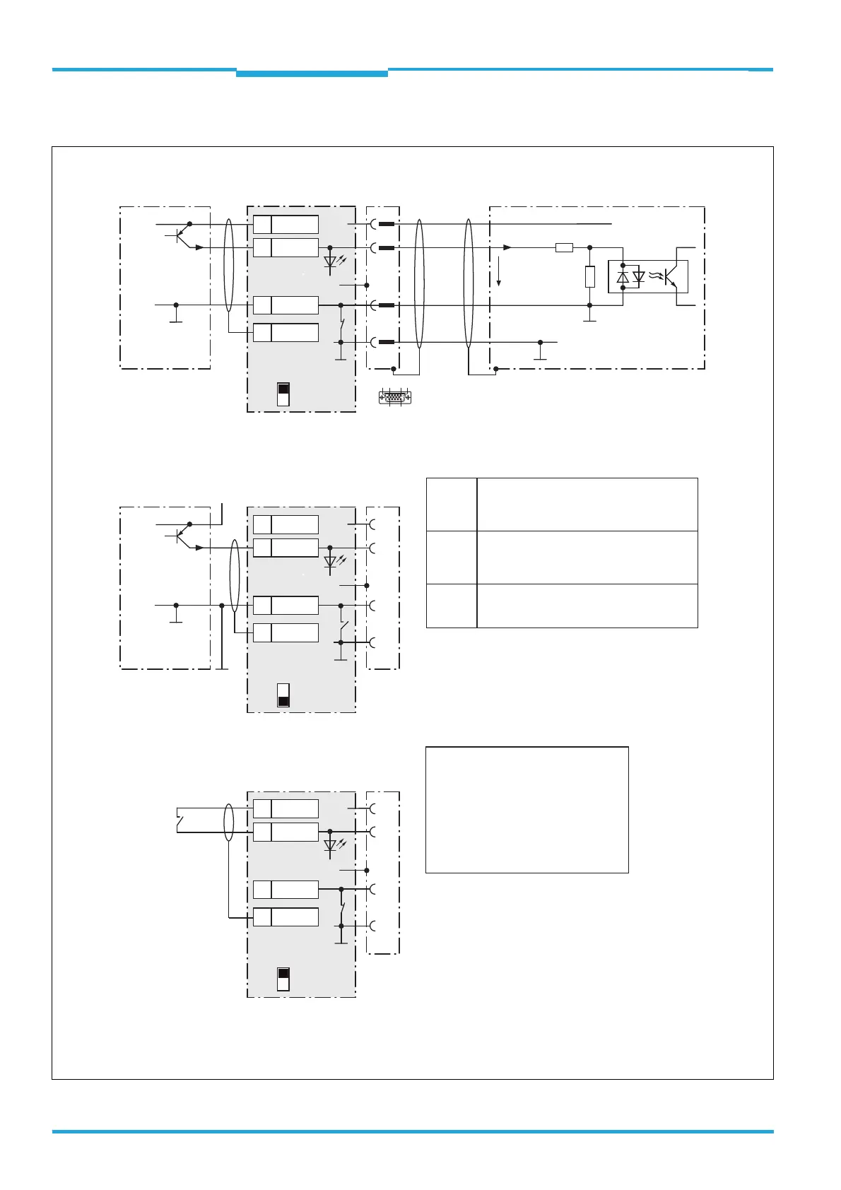
CLV61xCDM420-0001
PNP sensor
V
S
V
S
V
S
GND
SensGND
3.32 K
6.64 K
Sensor 2
V
in
+24 V* = DC 10 V to 30 V
a) Sensor supplied by CDM420-0001
b) Sensor connected electrically isolated/externally supplied
d) Switch connected electrically isolated/externally supplied
c) Switch supplied by CDM420-0001
4
15
1
5
Out
+24V*
+24V*
+24V*
GND
S6
e.g. photo-electric switch
CDM420-0001
PNP sensor
V
S
GND
Connect the switch as shown in b)
Out
GND
S6
e.g. photo-electric
switch
CDM420-0001
GND
S6
ON
OFF
S6 : SGND
ON
OFF
S6 : SGND
ON
OFF
S6 : SGND
V
S ext
Shield
D-Sub HD plug,
15-pin
GND
.
.
.
Shield
Shield
28
Sensor 2
27
SGND
7
Shield
29
+24 V*
28
Sensor 2
27
SGND
7
Shield
29
+24 V*
28
Sensor 2
27
SGND
7
Shield
29
+24 V*
V
in
= max. 32 V
Function assignment to "Sensor 2" switching input
via SOPAS ("Sensor/Input 2"):
- Start of reading clock
- Stop of reading clock
- Start teach-in matchcode/start code comparison
- Increment input
- if required further functions in the future
Ratings for "Sensor 2" switching input
SensGND
Switch S6: SGND-GND
ON: GND of the sensor connected to GND
of CDM420-0001/CLV61x.
OFF: GND of the sensor connected to
SensGND of CDM420-0001/CLV61x
(Sensor connected electrically isolated
to the CDM420-0001/CLV61x).
Selected reference potential valid for all
switching inputs ("Sensor 1/2" and "In 1/2")
Power fed to the input starts the assigned
function, e.g. stop of reading clock.
(default setting: logic not inverted (active high),
debouncing 10 ms)
– Optodecoupled, reverse polarity protected
– Can be wired with the PNP output of a sensor
– SensGND reference potential valid for all
switching inputs
Low: V
in
≤ 2 V; I
in
≤ 0.3 mA
High: 6 V ≤ V
in
≤ 32 V;
0.7 mA ≤ I
in
≤ 5 mA
Switching
behavior
Features
Electrical
values
GND

 Loading...


