RS-232
!
"
§
Device 1 Host
TxD
RxD
GND
RxD
TxD
GND
RS-422
$
%
&
/
(
Device 1 Host
RD+
TD+
RD‒
TD‒
GND
TD+
RD+
TD‒
RD‒
GND
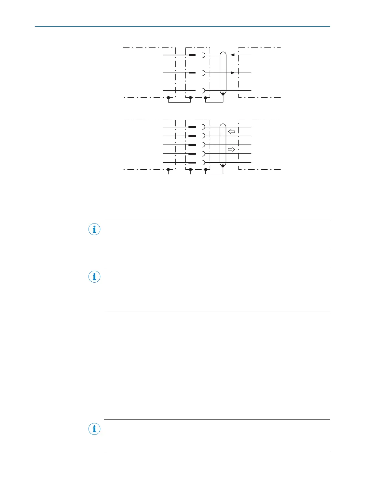
Figure 20: Wiring of the serial data interfaces RS-232 and RS-422
1
Device
!...§
Pin assignment: see RS-232 pin assignment for the respective device
$...(
Pin assignment: see RS-422 pin assignment for the respective device
NOTE
Activate the serial data interface type in the device using a configuration tool, e.g. the
SOPAS ET configuration software.
6.5.3 Wiring the CAN interface
NOTE
Activate the CAN data interface in the device with a configuration tool, e.g. the configu‐
ration software SOPAS ET.
Make further settings in the device corresponding to the function of the device in the
system configuration.
6.5.4 Wiring the digital outputs
Physical digital outputs on the device
The physical Result 1 and Result 4 digital outputs are used to signal events in the
read operation. Different functions can be assigned to them independently of each
other for this purpose. If the assigned event occurs, then the corresponding digital
output becomes live after the end of the read cycle for the selected pulse duration,
for example (default).
The four digital outputs are available at the following position in each case:
•
Male connector of the device (M12, 17-pin, A-coded)
•
Open end of the adapter cable (female connector, M12, 17-pin, A-coded/open
end)
NOTE
Provide an arc-suppression switch at the digital output if inductive load is present.
b
Attach a freewheeling diode directly to the load for this purpose.
6 ELECTRICAL INSTALLATION
38
O P E R A T I N G I N S T R U C T I O N S | GLS621 8024289/19E9/2020-10-21 | SICK
Subject to change without notice