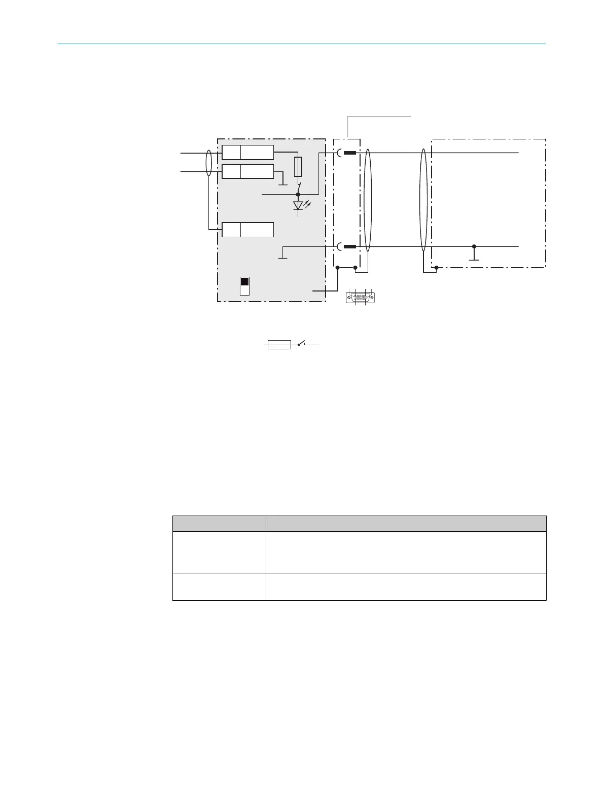
13.6.3 Connecting supply voltage for the device in CDB620-001
Device = Lector621 ECO = V2D621x-xxxxxYx (serial variant, Y = D or E)
V
S
- U
IN
-
F
S 1
- U
IN
*
4
V
s
1
Device
3CDB620-001
V
S
V
S
1
5
5
Shield
1 U
IN
2 GND
U
IN
*
GND
S1
F
Shield
GND
.
.
.
.
.
.
ON
OFF
S1 : POWER
U
IN
*
POWER
Cable 2
GND
110
15
6
11
5
Figure 63: Connecting supply voltage for the device in CDB620-001 connection module
1
Supply voltage V
S
2
Connecting cable permanently connected with the device (male connector, D-Sub-HD, 15-
pin)
3
Device
4
Connection module: female connector, D-Sub-HD, 15-pin
### or ###
Function of switch S1
Table 55: Switch S1: Power
Switch setting Function
ON Supply voltage U
IN
connected to CDB620-001 and device via fuse and
switch S1 as a supply voltage U
IN
*.
Supply voltage U
IN
* can be additionally tapped at terminals 11 and 14.
OFF CDB620-001 and device disconnected from supply voltage.
Recommended setting for all connection work.
13.6.4 Wiring serial host interface RS-232 of the device in CDB620-001
Device = Lector621 ECO = V2D621x-xxxxxYx (serial variant, Y = D or E)
13 ANNEX
106
O P E R A T I N G I N S T R U C T I O N S | Lector621 8022502/15NT/2020-02-11 | SICK
Subject to change without notice