7
Result 1 4
Result 2 4
- e.g. PLC 3
CMC600 parameter cloning module
(optional) 2
ONOFF
POWER
S1
0.8 A T
Term CAN
Term 485RS
SGND - GND
422 485
ONOFF
NO
YES
ONOFF
ONOFF
S2 S3
S7S6
S4
CMC
10 11 12 13 14 15 16 17 18
Sens 1
In 1
In 2
U
IN
*
U
IN
*
Sens 2
SGND
SGND
SGND
LEDs
20 21 22 23 24
Res 1
Res 2
Out 1
Out 2
GND
30 31 32 33 34
CAN_H
CAN_L
T+
R+
GND
40 41 42 43 44
CAN_H
CAN_L
T‒/TxD
R‒/RxD
GND
SCANNER
AUX interface 5
U
IN
U
IN
GND
GND
Shield
Shield
Shield
Shield
1 2 3 4 5 6 7 8
V
S
Out
GND
GND
RS-232
Pin
2: RxD
3: TxD
5: GND
Host
TD‒
TD+
RD+
RD‒
TxD
Host
RxD
GND
GND
RS-232
F
RS-422
CDB620-001
1
V
S
à
= ß
V
S
- U
IN
-
F
S 1
- U
IN
*
- PC
6
- Device 9
5
1
9
6
110
15
6
11
5
8
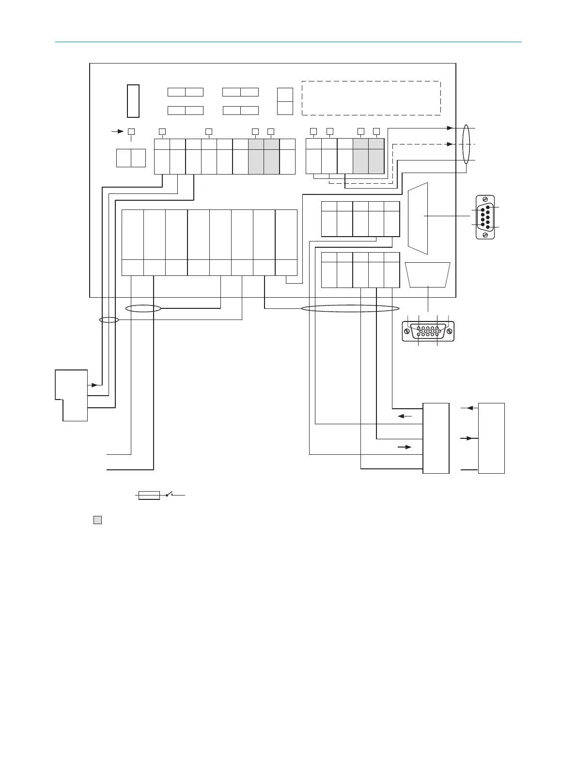
Figure 62: Overview: connection of device and peripherals to the CDB620-001 connection module
1
External trigger sensor, e.g. for read cycle generation
2
CMC600 parameter cloning module (optional)
3
e.g. PLC (programmable logic controller)
4
Name of the digital output
5
Auxiliary interface “Aux”
6
Male connector, D-Sub, 9-pin
7
SCANNER = Device
8
Female connector, D-Sub-HD, 15-pin
9
Device to be connected
ß
The optional CMC600 parameter cloning module is required in the connection module in order to be able to use the
additional external digital inputs and outputs of the device (highlighted in gray)
à
Supply voltage V
S
ANNEX 13
8022502/15NT/2020-02-11 | SICK O P E R A T I N G I N S T R U C T I O N S | Lector621
105
Subject to change without notice