Device
1 CDB620-001 Host
5
.
.
.
TxD
RxD
RxD
TxD
GND
GND
GND
9
7
43
T‒/TxD
44
R‒/RxD
42
GND
6
Shield
RS-232 RS-232
422
485
S6 : RS
ON
OFF
S7: Term 485
S6
422485
110
15
6
11
5
3
Cable 2
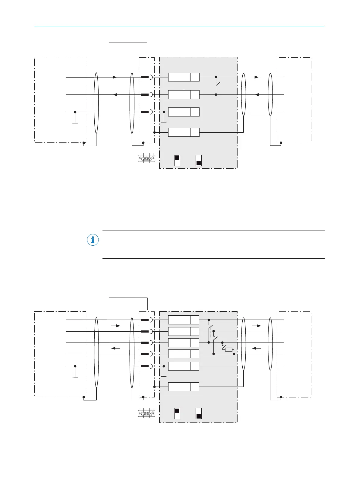
Figure 64: Wiring data interface RS-232 of the device in the connection module CDB620-001
1
Device
2
Connecting cable permanently connected with the device (male connector, D-Sub-HD, 15-pin)
3
Connection module: female connector, D-Sub-HD, 15-pin
NOTE
Activate the RS-232 data interface in the device with a configuration tool, e.g. the con‐
figuration software SOPAS ET.
13.6.5 Wiring serial host interface RS-422 of the device in CDB620-001
Device = Lector621 ECO = V2D621x-xxxxxYx (serial variant, Y = D or E)
Device
1 CDB620-001
Host
5
TD+
TD‒
RD+
RD‒
RD+
RD‒
TD+
TD‒
GND
GND
GND
8
9
6
7
33
T+
43
T‒/TxD
34
R+
44
R‒/RxD
42
GND
6
Shield
.
.
.
RS-422 RS-422
422
485
S6 : RS
ON
OFF
S7: Term 485
S6
422
S7
OFF
120 Ω
485
110
15
6
11
5
3
Cable 2
Figure 65: Wiring data interface RS-422 of the device in the connection module CDB620-001
ANNEX 13
8022502/15NT/2020-02-11 | SICK O P E R A T I N G I N S T R U C T I O N S | Lector621
107
Subject to change without notice