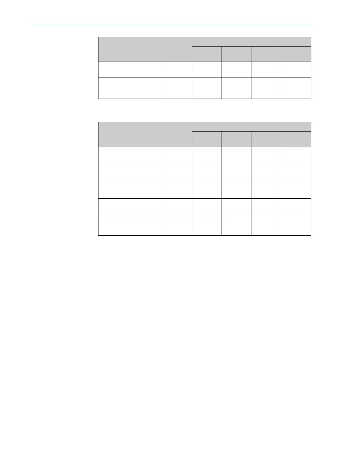
Designation Supply voltage (V
S
) in [DC V]
9.6
(12 V -20%)
12 24 28.8
(24 V +20%)
Typical, all 4 digital outputs
loaded (0.1 A per output)
I
B RMS 4Out
[A]
0.8 0.72 0.57 0.54
Power loss, all 4 digital out‐
puts loaded (0.1 A per out‐
put)
P
Peak 4Out
[W]
7.68 8.64 13.68 15.55
1)
For design of the power supply unit, supply cable and fuse protection at the start of the line.
Table 15: Typical current consumption depending on supply voltage (Lector621 ECO)
Designation Supply voltage (V
S
) in [DC V]
9.6
(12 V -20 %)
12 24 28.8
(24 V +20 %)
Current consumption, digi‐
tal outputs unloaded
I
B RMS
[A] 0.39 0.31 0.16 0.14
Power loss, digital outputs
unloaded
P
RMS
[W] 3.74 3.72 3.84 4.03
Maximum current con‐
sumption, digital outputs
unloaded
I
B Peak
[A] 1.05 0.90 0.45 0.35
Typical, both digital outputs
loaded (0.1 A per output)
I
B RMS 2Out
[A]
0.59 0.51 0.36 0.34
Power loss, all 2 digital out‐
puts loaded (0.1 A per out‐
put)
P
Peak 2Out
[W]
5.66 6.12 8.64 9.79
1)
For design of the power supply unit, supply cable and fuse protection at the start of the line.
Protecting the supply cables
To ensure protection against short-circuits/overload in the customer’s supply cables,
the wire cross-sections used must be appropriately selected and protected.
The following standards must be observed in Germany:
•
DIN VDE 0100 (part 430)
•
DIN VDE 0298 (part 4) and/or DIN VDE 0891 (part 1)
Connection without connection module
With a supply voltage of DC 12 V to 24 V ± 20%, protect the device with a separate fuse
with the following rating:
•
Lector621: 2 A
•
Lector621 ECO: 0.8 A
b
Install the fuse in the supply circuit at the start of the supply cable.
Connection with connection module
The supply voltage for the device is protected as follows in the connection modules in
the circuit after switch S1:
6 ELECTRICAL INSTALLATION
44
O P E R A T I N G I N S T R U C T I O N S | Lector621 8022502/15NT/2020-02-11 | SICK
Subject to change without notice