„V
S
”
“Host 1”
“Aux 1”
“Result 2”
“Result 1”
“CAN”
“Sensor 2”
“Sensor 1”
“AUX”
CAN bus
“Result 1”
“Result 2”
PLC
“External output 2”
CDM420-0006
Connection module 6
“Host 1”
“Aux 1”
RS-232
HOST/PLC
Further data
processing 8
PC
Configuration
Diagnostics
Image display
Interfaces 3
Device 2
“USB” (Aux 2) 4, Image transfer 5
RS-232/RS-422
USB
“Aux 2”
“Sensor 2”
“Sensor 1”
“External input 2”
“External input 1”
CMC600
1
ã
â
V
S
ß
= á
“External output 1”
à 9
7
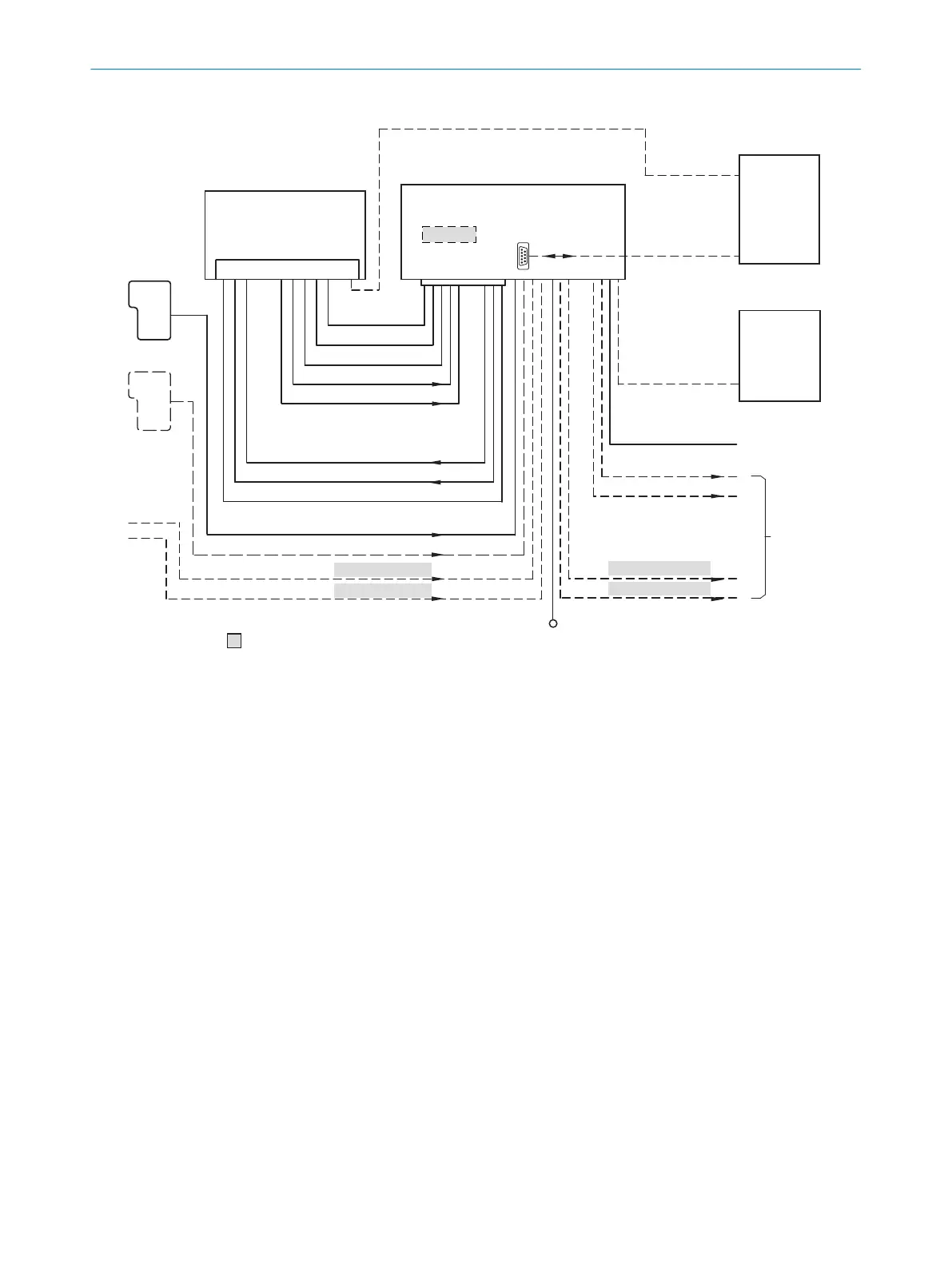
Figure 48: Connection of the device (serial variant) to peripherals via CDM420-0006 (overview)
1
External trigger sensor, e.g. for read cycle generation
2
Device
3
Interfaces
4
USB interface only for temporary use (service)
5
Image transmission
6
Connection modules
7
Configuration, diagnostics or image display
8
Data further processing
9
External digital outputs (switching)
ß
Supply voltage V
S
à
External digital inputs (switching)
á
The optional CMC600 parameter cloning module is required in the connection module in order to be able to use the
additional external digital inputs and outputs of the device (highlighted in gray)
â
Other functions
ã
Application-dependent alternative stop trigger (e.g. photoelectric sensor) or travel increment (incremental encoder)
ANNEX 13
8022502/15NT/2020-02-11 | SICK O P E R A T I N G I N S T R U C T I O N S | Lector621
89
Subject to change without notice