4
Input voltage V
in
5
Device
6
V2D621x-xxxxxYx (Ethernet variant, Y = B or C): male connector, M12, 17-pin, A-coded
7
Connection module: female connector, D-Sub-HD, 15-pin
8
e.g. photoelectric sensor
9
PNP sensor
ß
Supply voltage V
S
+24V*
CDM420-0006
PNP sensor 4
V
S
GND
Out
GND
S6
ON
OFF
S6 : SGND-GND
V
S ext
Shield
A
Sensor B
37
SGND
6
Shield
39
+24 V*
Trigger sensor 1
3
2
+24V*
CDM420-0006
GND
S6
ON
OFF
S6 : SGND-GND
Shield
A
Sensor B
37
SGND
6
Shield
39
+24 V*
1
V
S ext
GND
A
37
2
2
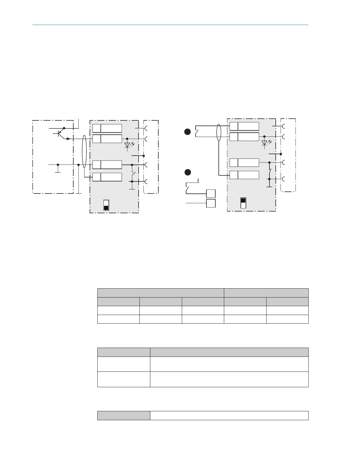
Figure 56: Left: Trigger sensor connected potential-free and supplied with power externally. Right: Alternatively switch,
!
sup‐
plied with power by connection module CDM420-0006 or
"
connected potential-free and supplied with power externally.
Switch setting S6 then as in left figure.
1
Trigger sensor, e.g. for read cycle generation
2
External supply voltage V
S ext
3
PNP sensor
4
Supply voltage V
S
Table 45: Assignment of placeholders to the digital inputs
CDM420-0006 Device
Terminal A Signal B Pin C Pin D Sensor E
38 Sensor 1 14 10 1
28 Sensor 2 4 15 2
Function of switch S6
Table 46: Switch S6: SGND - GND
Switch setting Function
ON GND of the trigger sensor connected with GND of CDM420-0006 and
GND of the device
OFF Trigger sensor connected potential-free at CDM420-0006 and device.
Common, isolated reference potential of all digital inputs is SGND.
Characteristic data of the digital inputs
Table 47: Characteristic data of the digital inputs “Sensor 1” and “Sensor 2”
Type Switching
ANNEX 13
8022502/15NT/2020-02-11 | SICK O P E R A T I N G I N S T R U C T I O N S | Lector621
97
Subject to change without notice