1
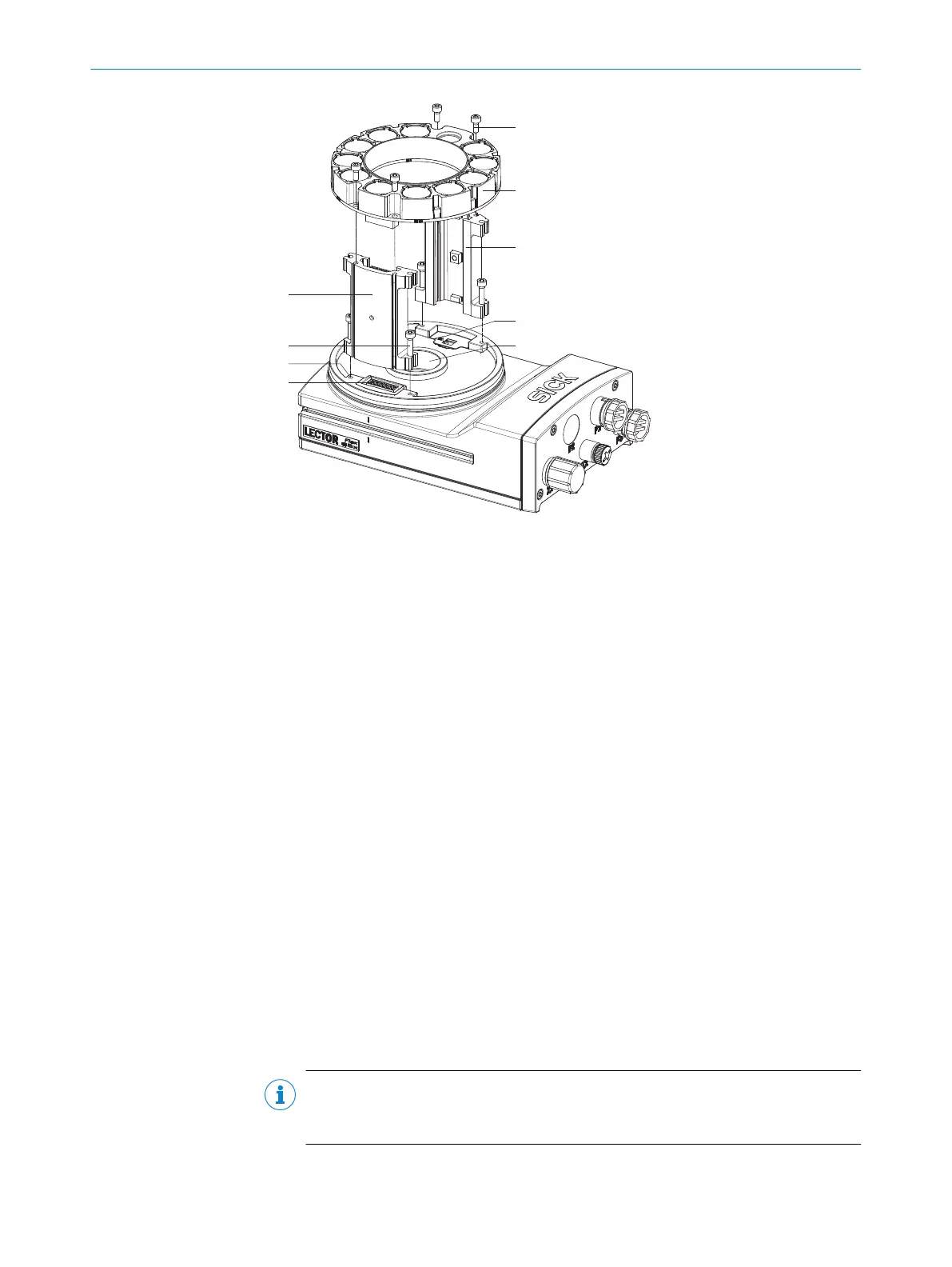
Spacer, left with electrical connection
2
4 tapped blind holes, M2.5, 5.5 mm deep, for mounting the spacer
3
4 x screws, long
4
Electrical connection for integratable ring illumination unit
5
4 screws, short
6
Integratable ring illumination unit
7
Spacer, right
8
Laser warning shield of the laser output aperture
9
Light inlet with threaded connection for lens
1. Switch off the supply voltage to the device.
2. Peel off the white protective sticker on the camera housing that covers the electri‐
cal connection for the ring illumination unit.
3. Place the camera housing on a nonslip base.
4. If required for the country in question, stick the French laser warning label sup‐
plied over the English laser warning label in the camera housing. Make sure to
stick the label exactly over the other one. For safety reasons, the English laser
warning label must not be removed.
5. Remove the protective cap from the round light inlet.
6. Carefully insert the optional filter and spacer disk into the light inlet.
7. Screw the lens unit into the C-mount thread until it engages. This will also lock the
optional filter in place at the same time.
8. Take two pairs of long screws and screw them into the tapped blind holes to
mount each spacer to the correct side of the camera housing.
9. Use the 4 short screws to mount the ring illumination unit to the two spacers.
10. Manually preset the sharpness and mask of the lens unit.
11. Check the setting of the SOPAS ET configuration software.
NOTE
If the required adjustments to the lens are not carried out immediately, mount the
optics protective hood for the lens.
MOUNTING 5
8016185/19E9/2020-10-21 | SICK O P E R A T I N G I N S T R U C T I O N S | Lector64x/65x Flex, Lector65x Dynamic Focus
27
Subject to change without notice