6.2.1 Data cables
NOTE
Layout of data cables
■
Use screened data cables with twisted-pair wires.
■
Implement the screening design correctly and completely.
■
To avoid interference, always use EMC-compliant cables and layouts. This applies,
for example, to cables for switched-mode power supplies, motors, clocked drives,
and contactors.
■
Do not lay cables over long distances in parallel with power supply cables and
motor cables in cable channels.
Serial data transmission (RS-232, RS422)
•
The possible length of cable between the device and host computer depends on
the following factors:
°
The physical version of the host interface selected
°
The data transmission rate set in the device
For further information, see "Wiring data interfaces", page 40.
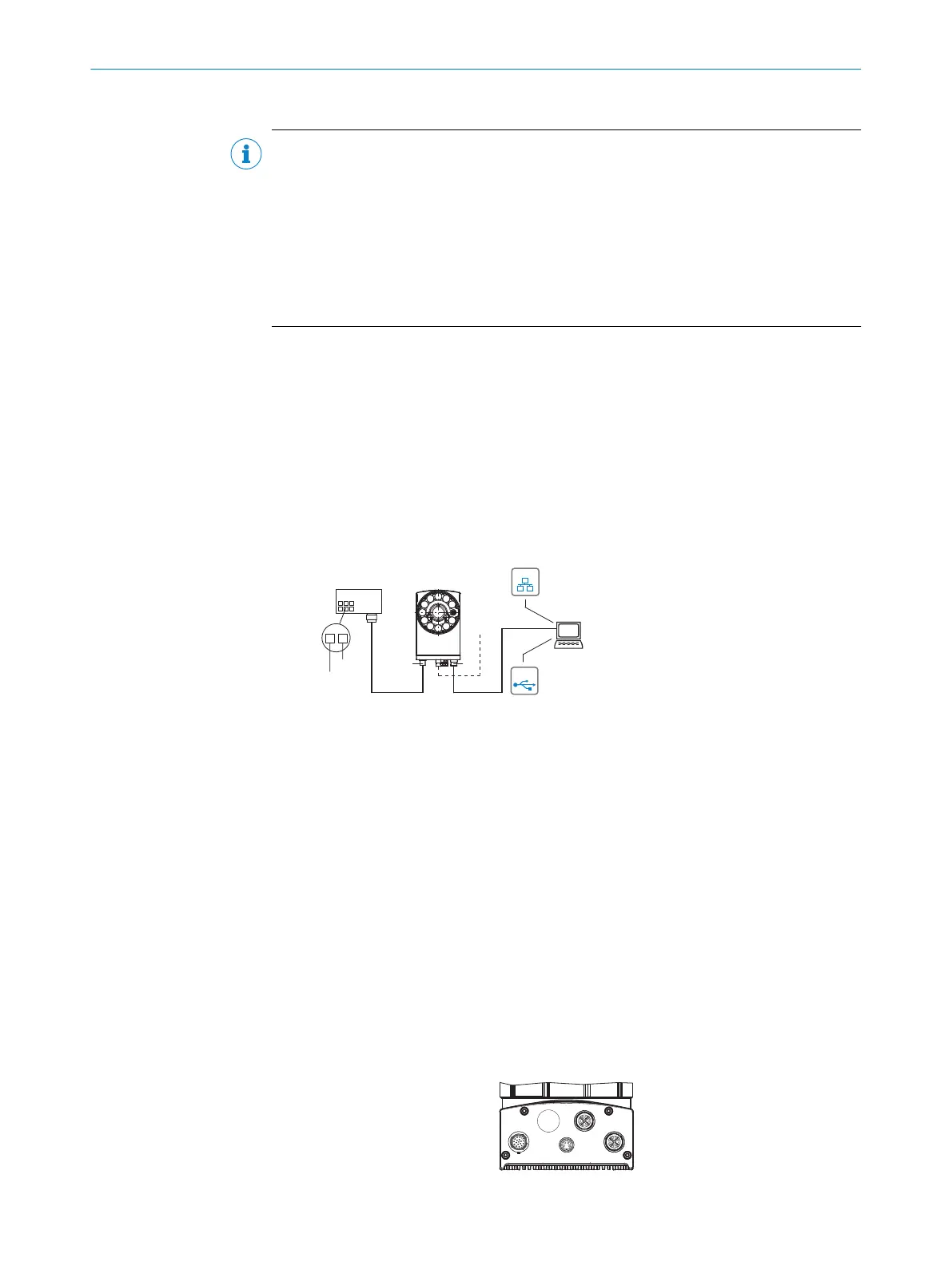
6.3 Connection principle
Connection with CDB650-204 connection module
SOPASSOPAS
Lector65x
Power... Ethernet
USB 2
...
...
1
2
DC 24 V ± 20 %
GND
USBUSB
EthernetEthernet
X1
P3
Lector64x
CDB650-204
Connection
module 1
Configuration 3
Image display 4
Diagnostics 5
Cable 6 Cable 7
Figure 12: Only valid for connection variant 1. Connection variants for Systems and DualPort are
not entirely taken into account in this view.
1
CDB650-204 connection module
2
Alternative USB cable: male connector, M8, 4-pin/male connector, USB-A, 4-pin
3
Configuration
4
Image display
5
Diagnostics
6
Cable: male connector, M12, 17-pin, A-coded/female connector, M12, 17-pin, A-coded
7
Cable: male connector, M12, 8-pin, X-coded/male connector, RJ45, 8-pin
Wiring without SICK connection module
When using customer-specific connection units, the wiring principle for the signals can
be found in the connection diagrams for the CDM420-0006 connection module, see
"Connection of the device to CDM420-0006", page 80.
6.4 Overview of the electrical connections
ELECTRICAL INSTALLATION 6
8016185/19E9/2020-10-21 | SICK O P E R A T I N G I N S T R U C T I O N S | Lector64x/65x Flex, Lector65x Dynamic Focus
37
Subject to change without notice