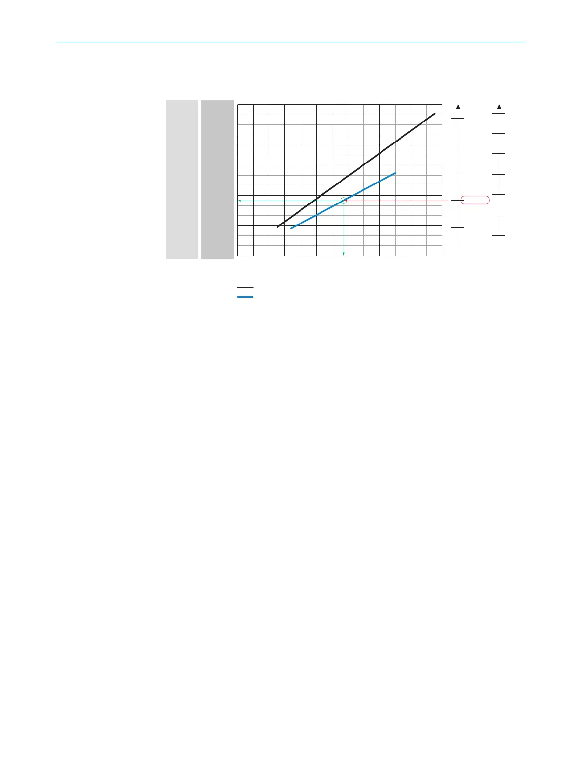
Lector65x Dynamic Focus
Field of view in mm²
0
Working distance/focus position in mm
150 x 75
300 x 150
600 x 300
750 x 375
450 x 225
Min. resolution in mm
1D code 2D code
0.2
0.3
0.1
0.2
0.4
0.6
0.4
0.3
0.1
0.5
0.5
0.7
f = 40 mm (V2D65xR-xxKxx)
f = 54 mm (V2D65xR-xxHxx)
V2D652R
V2D654R
1
45
3
2
0
150 x 150
300 x 300
600 x 600
750 x 750
450 x 500
0 200 600 1000 1400 1800 2200 2600
1
Field of view in mm
2
2
Minimum resolution in mm
3
1D code
4
2D code
5
Working distance/Focus position in mm
6
Selected code resolution
7
Focal length of lens, here for example for f = 54.0 mm
8
Reading off: resultant maximum working distance
9
Reading off: resultant field of view V2D652R (mm x mm)
10
Reading off: resultant field of view V2D654R (mm x mm)
5.6 Mounting the device
1. If required for the country in question, stick the French warning label supplied over
the English warning label for LED risk group RG 2.
2. Mount the device in a suitably prepared mounting system using the tapped blind
holes or sliding nuts provided (see "Device view", page 16) with at least 2 screws.
Screw the screws no more than 5 mm into the tapped blind holes or sliding nuts.
To do so, either use the 4 tapped blind holes on the rear of the device or the
two sliding nuts on the side of the device. Attach the separately-ordered, optional
SICK mounting system using the sliding nuts on the device. Mounting systems are
available as accessories, see "Accessories", page 66.
3. Align the device taking into consideration the field of view (see "Field of view
diagrams", page 29) and the application circumstances (see "Installation require‐
ments", page 25).
MOUNTING 5
8016185/19E9/2020-10-21 | SICK O P E R A T I N G I N S T R U C T I O N S | Lector64x/65x Flex, Lector65x Dynamic Focus
31
Subject to change without notice