9
External digital outputs
ß
Supply voltage V
S
à
External digital inputs
á
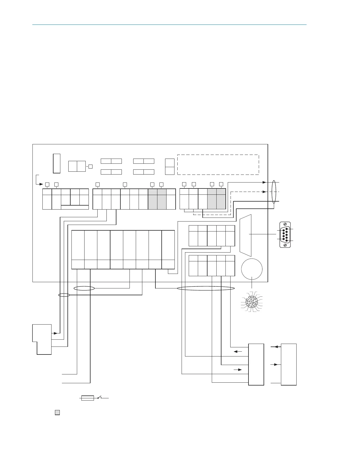
The optional CMC600 parameter cloning module is required in the connection module in order to be able to use the
additional external digital inputs and outputs of the device (highlighted in gray).
â
Other functions
ã
Application-dependent alternative stop trigger (e.g. photoelectric sensor) or travel increment (incremental encoder)
13.2.2 Wiring overview of the CDB650-204
Device = Lector64x = V2D64xx-xxxxYx (Y = A, B or S), 1 digital input used
Device = Lector65x = V2D65xx-xxxxYx (Y = A, B or S), 1 digital input used
CMC600 parameter cloning module
(optional) 2
Term CAN
Term 485RS
SGND - GND
422 485
ONOFF
NO
YES
ONOFF
ONOFF
S2 S3
S7S6
S4
CMC
ONOFF
POWER
S1
30 31 32 33 34
CAN_H
CAN_L
T+
R+
GND
40 41 42 43 44
CAN_H
CAN_L
T‒/TxD
R‒/RxD
GND
AUX interface 5
U
IN
U
IN
GND
GND
Shield
Shield
Shield
Shield
1 2 3 4 5 6 7 8
LEDs
= ß
V
S
V
S
Out
GND
Result 1 4
- e.g. PLC 3
GND
Result 2 4
- Device 9
Pin
2: RxD
3: TxD
5: GND
Host
TD‒
TD+
RD+
RD‒
TxD
Host
RxD
GND
GND
RS-232
2 A T
F
SENSOR
50 51 52 53 54
RES/
OUT 3
RES/
OUT 4
Ext. Illum.
TR
L+
GND
20 21 22 23 24
GND
RES/
OUT 1
RES/
OUT 2
EXT.
OUT 1
EXT.
OUT 2
10 11 12 13 14 15 16 17 18
U
IN
*
U
IN
*
SGND
SGND
SGND
EXT.
IN 1
SENS/
IN 1
SENS/
IN 2
EXT.
IN 2
RS-232
3
1
7
2
6
5
4
8
13
14
17
15
9
10
12
16
11
8
1
CDB650-204
V
S
- U
IN
-
F
S 1
- U
IN
*
- PC
6
7
à
5
1
9
6
RS-422
Figure 19: Connection of device and peripherals to the CDB650-204 connection module (overview)
13
ANNEX
68
O P E R A T I N G I N S T R U C T I O N S | Lector64x/65x Flex, Lector65x Dynamic Focus 8016185/19E9/2020-10-21 | SICK
Subject to change without notice