Function of switch S1
Table 16: Switch S1: Power
Switch setting Function
ON Supply voltage U
IN
connected to CDB650-204 and device via fuse and
switch S1 as a supply voltage U
IN
*.
Supply voltage U
IN
* can be additionally tapped at terminals 11 and 14.
OFF CDB650-204 and device disconnected from supply voltage.
Recommended setting for all connection work.
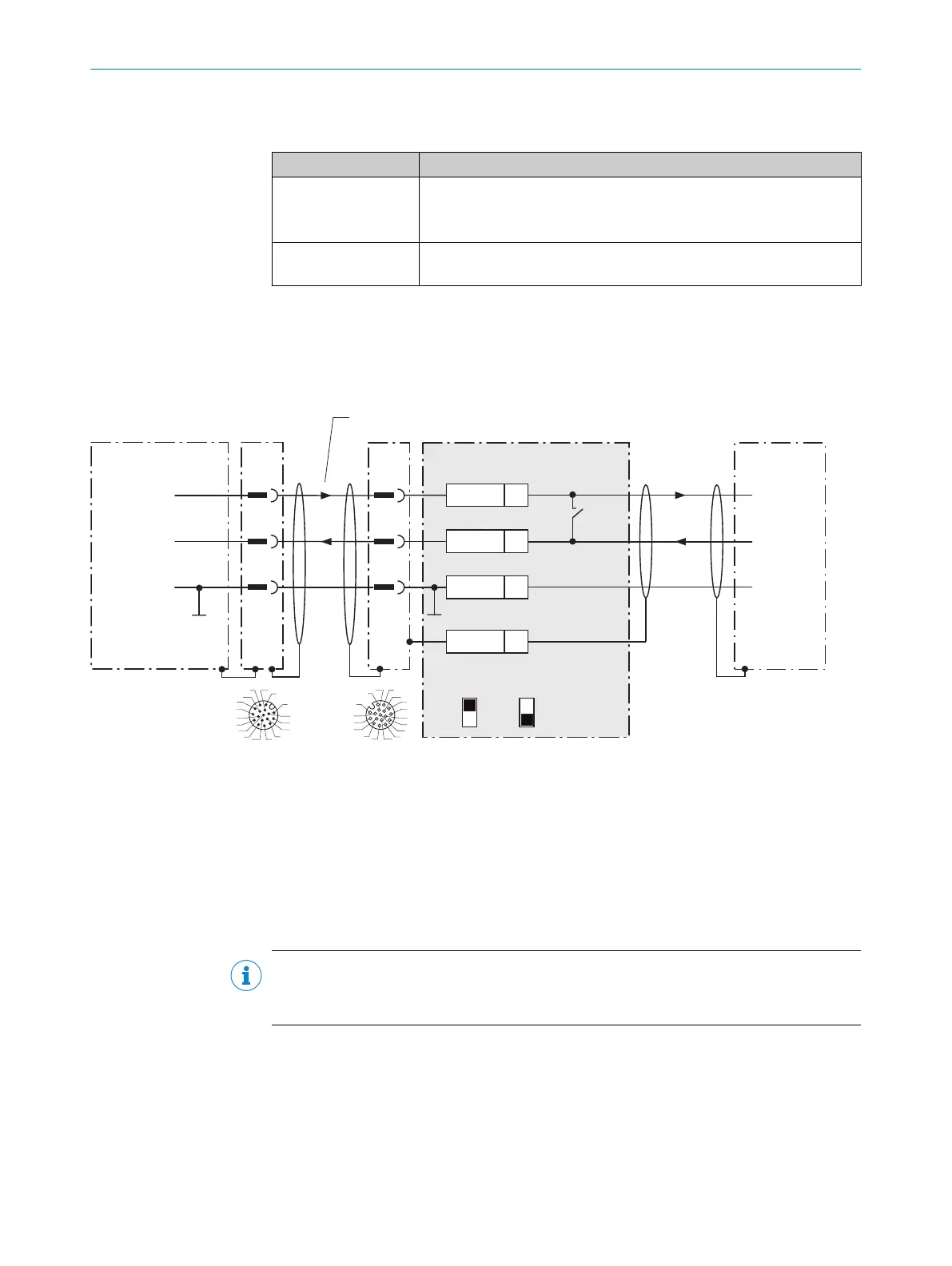
13.2.4 Wiring serial host interface RS-232 of the device in CDB650-204
Device = Lector64x = V2D64xx-xxxxYx (Y = A, B or S)
Device = Lector65x = V2D65xx-xxxxYx (Y = A, B or S)
Device 1 CDB650-204 Host
1
.
.
.
TxD
RxD
RxD
TxD
GND
GND
GND
12
1
6
12
6
43
T‒/TxD
44
R‒/RxD
42
GND
6
Shield
RS-232 RS-232
422
485
S6 : RS
ON
OFF
S7: Term 485
S6
422485
3
1
7
2
6
5
4
8
13
14
17
15
9
10
12
16
11
3
1
7
2
6
5
4
8
13
14
17
15
9
10
12
16
11
Cable 2
4 3
Figure 21: Wiring data interface RS-232 of the device in the connection module CDB650-204
1
Device
2
Connection cable 1:1 (female connector, M12, 17-pin, A-coded/male connector, M12, 17-pin, A-coded)
3
Connection module: female connector, M12, 17-pin, A-coded
4
Device: male connector, M12, 17-pin, A-coded
NOTE
Activate the RS-232 data interface in the device with a configuration tool, e.g. the
configuration software SOPAS ET.
13.2.5 Wiring serial host interface RS-422 of the device in CDB650-204
Device = Lector64x = V2D64xx-xxxxYx (Y = A, B or S)
Device = Lector65x = V2D65xx-xxxxYx (Y = A, B or S)
13 ANNEX
70
O P E R A T I N G I N S T R U C T I O N S | Lector64x/65x Flex, Lector65x Dynamic Focus 8016185/19E9/2020-10-21 | SICK
Subject to change without notice