Electrical values Low: V
in
1)
≤ 2 V; I
in
2)
≤ 0.3 mA
High: 6 V ≤ V
in
≤ 30 V; 0.7 mA ≤ I
in
≤ 5 mA
1)
Input voltage.
2)
Input current.
NOTE
Assign the functions for the digital inputs in the device using a configuration tool, e.g.
the configuration software SOPAS ET.
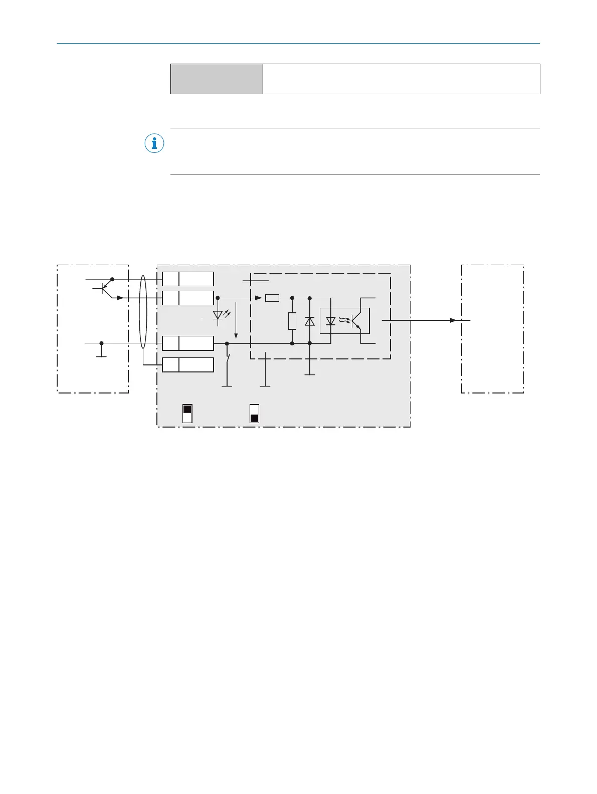
13.2.8 Wiring the external digital inputs of the device in the CDB650-204
Device = Lector64x = V2D64xx-xxxxYx (Y = A, B or S)
Device = Lector65x = V2D65xx-xxxxYx (Y = A, B or S)
Device 4CDB650-204
PNP sensor 7
V
S
GND
3.32 K
6.64 K
18
SGND
8
Shield
11
U
IN
*
A
Out
GND
S3
E.g. photo-electric
switch 6
Trigger sensor 1
CMC600 3
U
IN
*
Aux
(RS-232)
ON
OFF
S3 : SGND-GND
No
YES
S4 : CMC
V
in
“External
input C” 5
SensGND
EXT. IN B
8
2
Figure 26: Trigger sensor supplied with power by connection module CDB650-204
1
Trigger sensor, e.g. for read cycle generation
2
Input voltage V
in
3
The optional CMC600 parameter cloning module is required in the connection module in order to be able to use the
additional external digital inputs and outputs of the device
4
Device
5
Logical “External input” in the device
6
e.g. photoelectric sensor
7
PNP sensor
8
Supply voltage V
S
ANNEX 13
8016185/19E9/2020-10-21 | SICK O P E R A T I N G I N S T R U C T I O N S | Lector64x/65x Flex, Lector65x Dynamic Focus
75
Subject to change without notice