Characteristic data of the digital inputs
Table 23: Characteristic data of the digital inputs “External input 1” and “External input 2”
Type Switching
Switching behavior Power to the input starts the assigned function, e.g. start read cycle.
Default setting in the device: logic not inverted (active high), debounce
time 10 ms
Properties
•
Opto-decoupled, reverse polarity protected
•
Can be wired with PNP output of a trigger sensor
Electrical values Low: V
in
1)
≤ 2 V; I
in
2)
≤ 0.3 mA
High: 6 V ≤ V
in
≤ 30 V; 0.7 mA ≤ I
in
≤ 5 mA
1)
Input voltage.
2)
Input current.
NOTE
Assign the functions for the external digital inputs in the device using a configuration
tool, e.g., the SOPAS ET configuration software.
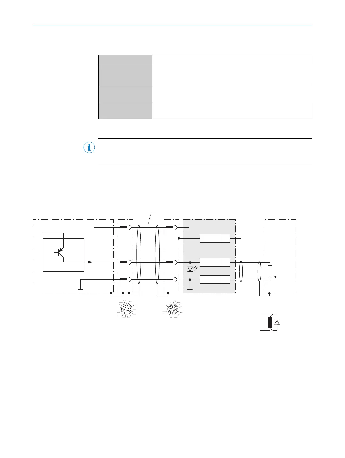
13.2.9 Wiring digital outputs of the device in the CDB650-204
Device = Lector64x = V2D64xx-xxxxYx (Y = A, B or S)
Device = Lector65x = V2D65xx-xxxxYx (Y = A, B or S)
Device 1
CDB650-204
Load (e.g. PLC) 4
Cable 3
B
1
.
.
.
D
22
GND
5Shield
U
IN
*V
S
GND
V
out
Result A
GND
B
1
2 2
For inductive load: 6
3
1
7
2
6
5
4
8
13
14
17
15
9
10
12
16
11
3
1
7
2
6
5
4
8
13
14
17
15
9
10
12
16
11
RES/OUT C
8 7
2
5
Figure 28: Wiring the digital outputs “Result 1” to “Result 4” of the device in the connection module CDB650-204
1
Device
2
Supply voltage V
S
3
Connection cable 1:1 (female connector, M12, 17-pin, A-coded/male connector, M12, 17-pin, A-coded)
4
Load (e.g. PLC)
5
Output voltage V
out
6
With inductive load: see note
7
Connection module: female connector, M12, 17-pin, A-coded
8
Device: male connector, M12, 17-pin, A-coded
ANNEX 13
8016185/19E9/2020-10-21 | SICK O P E R A T I N G I N S T R U C T I O N S | Lector64x/65x Flex, Lector65x Dynamic Focus
77
Subject to change without notice