Load (e.g. PLC) 4
GND
For inductive load: 6
V
out
Device 1
Aux
(RS-232)
CDM420-0006
CMC600 3
+24 V* (V
S
)
CAux Out B
36
GND
6
Shield
“External
output A” 2
5
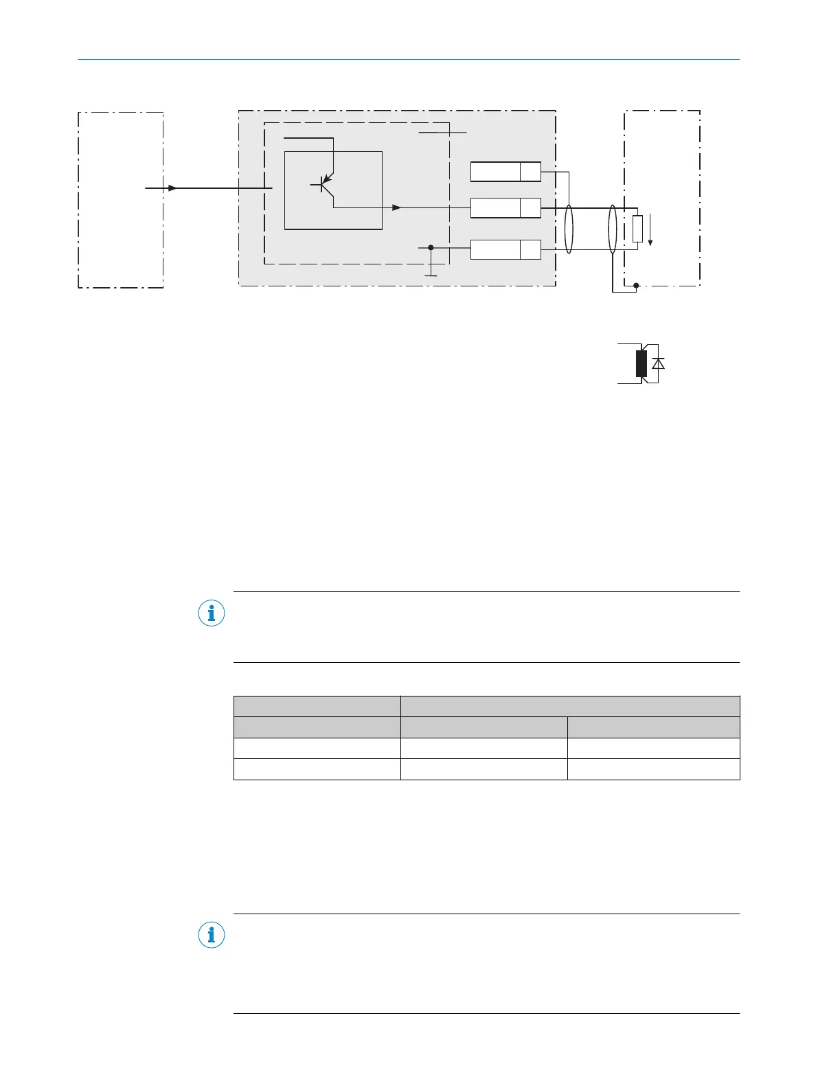
Figure 41: Wiring external digital outputs “Aux Out 1” and “Aux Out 2” of the device in the connection module CDM420-0006
1
Device
2
Logical “External output” in the device
3
The optional CMC600 parameter cloning module is required in the connection module in order to be able to use the
additional external digital inputs and outputs of the device
4
Load (e.g. PLC)
5
Output voltage V
out
6
With inductive load: see note
Inductive load
NOTE
Provide an arc-suppression switch at the digital output if inductive load is present.
b
Attach a freewheeling diode directly to the load for this purpose.
Table 38: Assignment of placeholders to the digital outputs
Device CDM420-0006
External output A Signal B Terminal C
1 Aux Out 1 40
2 Aux Out 2 30
Functional principle of the external digital outputs
The optional CMC600 parameter cloning module in combination with the CDB or CDM
connection module offers two additional digital outputs for the device. The outputs are
available at the respective terminals of the connection module. To distinguish them
from the physical digital outputs directly on the device, these addition outputs via the
CMC600 are designated as “external outputs”.
NOTE
The device transmits the statuses of its logical outputs to the CMC600 via its serial
data interface. The CMC600 converts the statuses into switching signals on its physical
digital outputs.
The digital outputs are not suitable for time-critical applications.
ANNEX 13
8016185/19E9/2020-10-21 | SICK O P E R A T I N G I N S T R U C T I O N S | Lector64x/65x Flex, Lector65x Dynamic Focus
93
Subject to change without notice