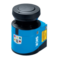
CAN IN connection
Figure 15: Male connector M12, 5-pin, A-coded
Pin Description Wire colors connecting cables part no.
6021166 or 6053042
1
1 Shield –
2 V
s
24 V DC ± 25% Red
3 Ground Black
4 CAN high White
5 CAN low Blue
1
Example values when using the specified connecting cable(s). Signal assignment and wire colors can
vary when using other connecting cables.
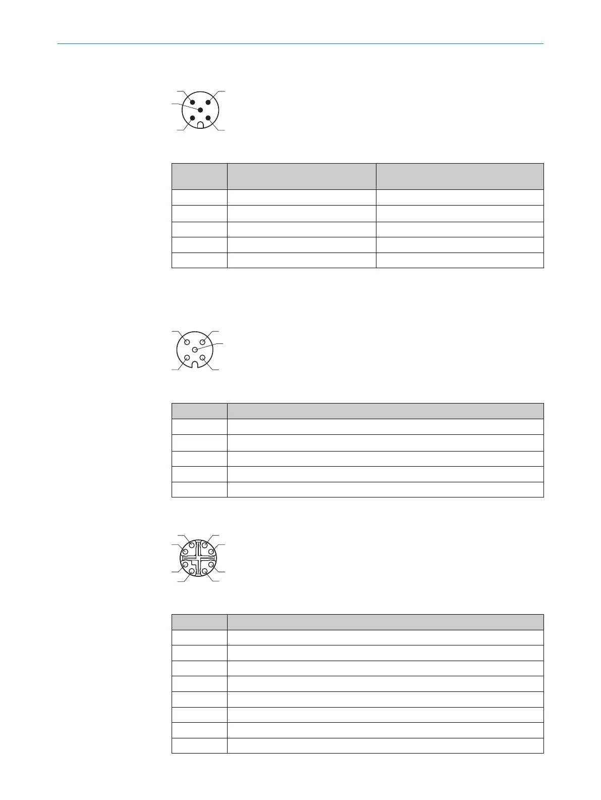
CAN OUT connection
Figure 16: Female connector M12, 5-pin, A-coded
Pin Description
1 Shield
2 V
out
24 V DC ± 25% (identical to V
s
)
3 GND
4 CAN high
5 CAN low
Ethernet connection
Figure 17: Female connector M12, 8-pin, X-coded
Pin Description
1 TRD0_P
2 TRD0_N
3 TRD1_P
4 TRD1_N
5 TRD3_P
6 TRD3_N
7 TRD2_P
8 TRD2_N
ELECTRICAL INSTALLATION 6
8023202/16S6/2020-01-24 | SICK O P E R A T I N G I N S T R U C T I O N S | LMS4400/LMS4500
33
Subject to change without notice