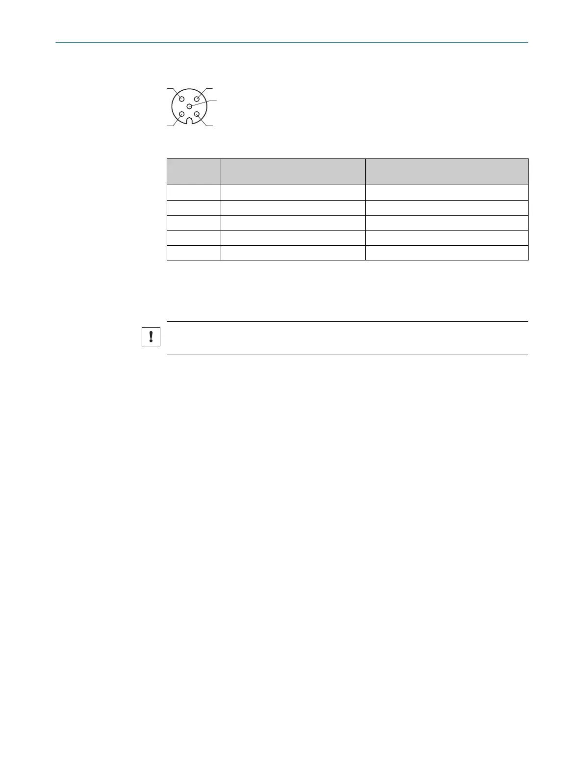
Encoder connection
Figure 18: Female connector M12, 5-pin, A-coded
Pin Description Wire colors connecting cable part no.
2097305
1
1 V
out
24 V DC ± 25% (identical to V
s
) Brown
2 Encoder B White
3 Ground Blue
4 Encoder A Black
5 Motor Sync Gray
1
Example values when using the specified connecting cable(s). Signal assignment and wire colors can
vary when using other connecting cables.
6.4 Connecting the device electrically
NOTICE
Observe the wiring instructions, see "Wiring notes", page 29.
1. Ensure the voltage supply is not connected.
2. Connect the device according to the connection diagram, see "Connection dia‐
gram", page 32.
6 ELECTRICAL INSTALLATION
34
O P E R A T I N G I N S T R U C T I O N S | LMS4400/LMS4500 8023202/16S6/2020-01-24 | SICK
Subject to change without notice