Once the measured value telegram has been confirmed, the first measured value is not
output until after the configured number of scans. Therefore, there is always a time
delay equivalent to the number of scans configured for averaging. The digit of the first
scan included in the averaging calculation is always output in the scan counter. Invalid
distance values (= 0) are not included in the averaging calculation, so that in these
places a smaller number of scans is used in the division calculation. The measured val‐
ues from other channels (remission, angle correction, quality) are not averaged;
instead, the value of the first scan from each channel is output.
Based on the scanning frequency of 600 Hz, a measured value is generated every
1.67 ms. The time delay affecting data output results from this base value multiplied by
the number of averaging operations (e.g., 2 averaging operations = 3.34 ms,
10 averaging operations = 16.67 ms). This time delay is not increased if the median
filter is activated at the same time.
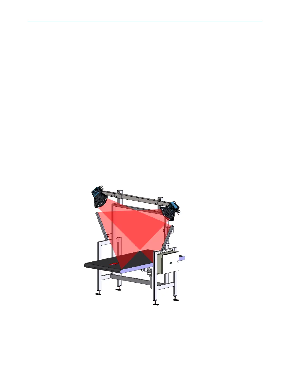
3.5.9 Motor synchronization for measuring range extension
Based on the technical and geometrical properties of the device, objects up to 1 m in
height can be measured continuously on a width of approx. 2.6 m. At a height of up to
2 m, a continuous width of approx. 1.4 m is achievable.
To increase the width of the field for the intended application or to avoid shadowing
effects caused by geometrical properties, multiple devices can be mounted side by side
at the same level.
To avoid mutual optical interference of adjacent sensors (beam dazzle or reflection),
the motors can be synchronized. The devices must have the same orientation when
doing so.
Figure 10: Mounting 2 LMS4000 LiDAR sensors side by side (example)
If you are using motor synchronization, please note:
•
The slave devices do not send feedback to the master. The Sync LED on the mas‐
ter lights up as soon as the sync signal is sent. The Sync LED on the slave starts
flashing as soon as a sync signal is received and lights up permanently once the
motors have been synchronized.
•
If devices are mounted exactly in parallel (angle of rotation = 0°), the default set‐
ting for the phase at the slave can usually be left unchanged at 0°.
PRODUCT DESCRIPTION
3
8023202/16S6/2020-01-24 | SICK O P E R A T I N G I N S T R U C T I O N S | LMS4400/LMS4500
23
Subject to change without notice