Preventive Maintenance
12 MCS100E HW Maintenance Manual 8009624/2009-09 (V1.4) ©SICKMAIHAKGmbH
3.1
Visual inspection
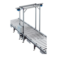
3.1.1 Peripheral equipment
3.1.2 MCS100E HW system cabinet
3.2 Check sample gas flow
1 View the "bar graph" display (F2 key).
2 View the "flow" bar graph (if necessary, press the "right" cursor key).
3 Check the data for sample gas flow in the control room.
4 Enter the data for sample gas flow in the logbook.
3.3 Check zero gas flow
1 View the "bar graph" display (F2 key).
2 Switch the MCS100E HW to "Stand-by". To do this:
–Press the F3 function key.
– Select "System Stop" (confirm safety prompt with "Yes").
– Exit the menu with "ESC" (otherwise the diagram will not be updated).
3 View the "flow" bar graph (if necessary, press the "right" cursor key).
4 Check the data for zero gas flow in the control room.
5 Enter the data for zero gas flow in the logbook.
6 Switch the MCS100E HW to measuring mode.
–Press the F3 function key.
– Select "System Start" (confirm safety prompt with "Yes").
– Exit the menu with "ESC".
Subassembly (as fitted) Check
Sampling point Condition, heating, continuity, filter
Sample gas line Condition, heating, continuity
What is to be checked Check
Ambient conditions
Installation location, ambient temperature, air
humidity, corrosive atmosphere.
Tubing Cracks, porous, brittle?
Enclosure and inside of device
Soiled, corroded? Loose parts? Odor? Unusual
noise?
Are service and fault messages
shown on the display?
----