Electrical installation
46 © SICK AG · Germany · All rights reserved · Subject to change without notice
8013889/ZML0/2017-06-
09
Operating Instructions
NAV350 Laser positioning sensor
Chapter 5
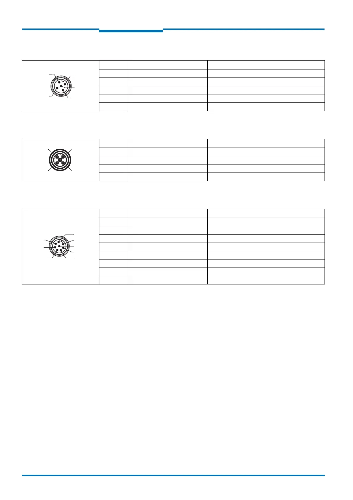
“Power” connection M12×5, plug, A coded
“Ethernet” connection M12×4, socket, D coded
“RS232” connection M12×8, plug, A coded
5.3 Preparing the electrical installation
5.3.1 Supply voltage
DC 24 V ±15% as per IEC 60364-4-41 (pay attention to permitted cable lengths in tab. 12
on page 47)
The NAV350 draws the following power:
• on switching on without switching outputs wired maximum 36 W
• in operation typically 12 W, plus a maximum of 12 W with switching output wired
The supply of power/the external power supply for the supply of power must be able to
provide at least 40 W continuous power, if the switching output is wired at least 48 W
continuous power.
Pin Signal Function
1V
S
Supply voltage NAV350
2V
S
Supply voltage NAV350
3GND Ground
4 OUT 24 V Digital output 1
5GND Ground
Tab. 9: Pin assignment of the “Power” connection on the NAV350
Pin Signal Function
1 Ethernet_TX+ Ethernet interface
2 Ethernet_RX+ Ethernet interface
3 Ethernet_TX– Ethernet interface
4 Ethernet_RX– Ethernet interface
Tab. 10: Pin assignment of the “Ethernet” connection on the NAV350
1
2
4
3
Pin Signal Function
1 RxD Serial RS232 host interface (receiver)
2 TxD Serial RS232 host interface (sender)
3– Do not use
4– Do not use
5 GND RS-232 Ground RS-232
6– Do not use
7– Do not use
8– Do not use
Tab. 11: Pin assignment of the “RS232” connection on the NAV350

 Loading...


