Chapter 3 Operating Instructions
V200/V300
16 © SICK AG • Industrial Safety Systems • Germany • All rights reserved 8012227/YT87/2016-03-29
Subject to change without notice
Product description
If the system is unable to change to a safe operational state (e.g. after contactor failure),
the system locks and shuts down completely (“lock-out”, see page 50). The electrical
connection for the external device monitoring is described in section 5.3 on page 33. The
configuration of the external device monitoring is described in chapter 8 “Configuration”
on page 44.
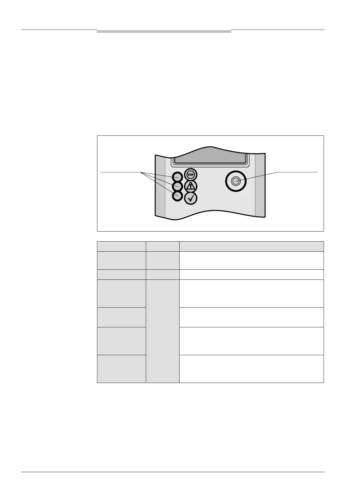
3.5 Status indicators
The light emitting diodes (LEDs) on the V200/V300 signal its operating status.
3.5.1 Status LEDs of the V200/V300
Display Colour Meaning
Ê O
Red
OSSDs shut down (e.g. if object in protective field or
“lock-out”)
Ë O
Green OSSDs activated. Protective field unoccupied
É O
No valid configuration taught-in (default delivery status)
⋅ Perform the teach-in procedure (see section 8.1
“Teach-in” on page 44).
É ôFõ
Even flashing: reset required
⋅ Press the reset button.
É ôJõ
Warning
⋅ Carry out a fault diagnosis (see chapter 10 “Fault
diagnosis” on page 50).
É ôKõ
Yellow
Error
⋅ Carry out a fault diagnosis (see chapter 10 “Fault
diagnosis” on page 50).
Note
of the V200/V300
LEDs of the V200/V300
Ê “Stop”
É “Warning”
Ë “OK”
teach-in key