Chapter 5 Operating Instructions
V200/V300
32 © SICK AG • Industrial Safety Systems • Germany • All rights reserved 8012227/YT87/2016-03-29
Subject to change without notice
Electrical installation
• To meet the requirements of the relevant product standards (e.g. IEC 61 496-1), the
external voltage supply for the devices (SELV) must be able to bridge a brief mains
failure of 20 ms. Power supplies according to EN 60 204-1 satisfy this requirement.
Suitable power supplies are available as accessories from SICK (see section 12.2
“Accessories” on page 59).
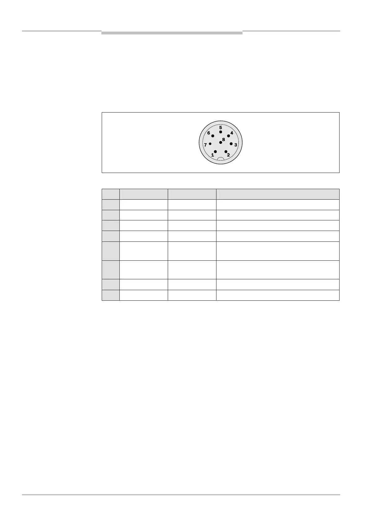
5.1 System connection M12 × 8
The V200/V300 has a hard-wired cable (length: approx. 30 cm) with a cable plug M12 × 8.
Pin Colour Signal Function
1 White RESTART Reset/restart (optional)
2 Brown +24 V DC 24 V DC (voltage supply)
3 Green TEACH/SYNC Teach-in/synchronisation
4 Yellow EDM External device monitoring (EDM) (optional)
5 Grey OSSD1
OSSD1 (safe output signal switching
device 1)
6 Pink OSSD2
OSSD2 (safe output signal switching
device 2)
7 Blue GND 0 V DC (voltage supply)
8 – FE Functional earth
Connecting cables of different length are available as accessories from SICK (see
section 12.2 “Accessories” on page 59). If you use connecting cables you have assembled
yourself, ensure the functional earth (pin 8) is connected.
V200/V300
system connection
V200/V300
Note