Chapter 4 Operating Instructions
V200/V300
18 © SICK AG • Industrial Safety Systems • Germany • All rights reserved 8012227/YT87/2016-03-29
Subject to change without notice
Mounting
4 Mounting
This chapter describes the preparation and completion of the mounting of the V200/V300
safety camera system. Mounting requires the following steps:
• checking the dimensions of the protective field (see below)
• determining the minimum distance (see page 20)
• mounting of the camera (see page 24)
• mounting the reflective tape (see page 29)
The following steps are necessary after mounting:
• completing the electrical connections (see chapter 5 on page 31)
• testing the installation (see section 7.1 on page 42)
4.1 Checking the dimensions of the protective field
Only use the V200/V300 safety camera system if the ratio allowed for the lengths of
the sides of the protective field can be met!
If the maximum ratio of the lengths of the sides is exceeded, the safety camera system
may not operate correctly. This would mean that the operator is at risk.
Applicable to all resolutions:
• The ratio of the lengths of the sides of a protective field monitored must not exceed 2:1.
• If you require a larger protective field than is possible with a single V200/V300, you can
mount two V200/V300 in parallel in opposite directions. In this way you can generate
two overlapping protective fields (see 6.2 “Application with two V200/V300” on
page 39).
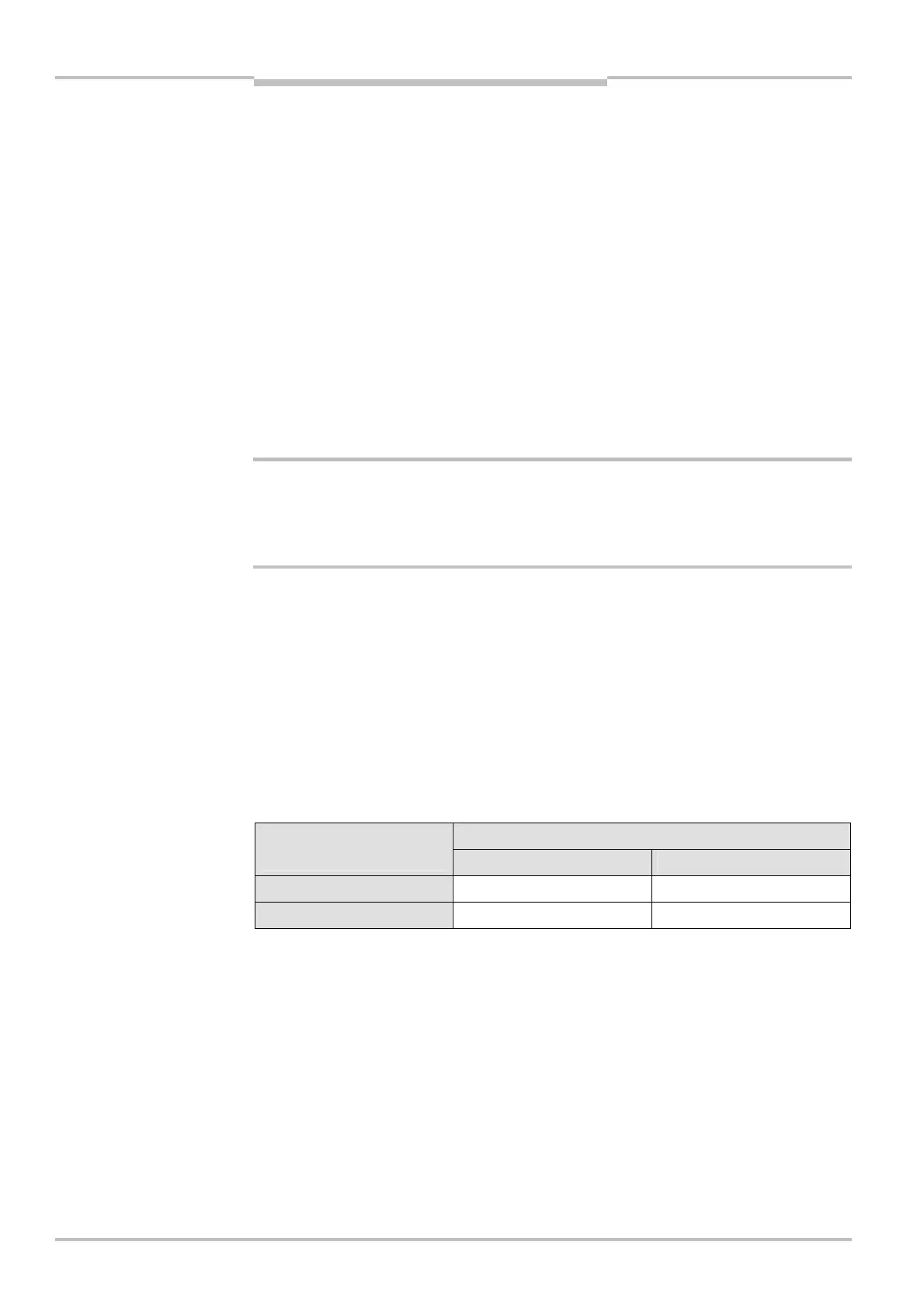
4.1.1 Protective field dimensions allowed at a resolution of 20 mm
The lengths of the sides of a protective field monitored must not be shorter than 0.40 m
and not longer than 1.00 m.
Longer side of the protective field
Shorter side of the
protective field
Minimum Maximum
″ 0.40 m … < 0.50 m = shorter side 2 × shorter side
″ 0.50 m … ′ 1.00 m = shorter side 1.00 m
Example 1: The shorter side is 0.43 m long. Then the longer side must be at least 0.43 m
and is allowed to be a maximum of 2 × 0.43 m = 0.86 m long.
Example 2: The shorter side is 0.78 m long. Then the longer side must be at least 0.78 m
and is allowed to be a maximum of 1.00 m long.
a
WARNING
Note
dimensions allowed for a
rectangular protective field
at a resolution of 20 mm
(intermediate values are
allowed)