7SR11 & 7SR12 Description Of Operation
©2012 Siemens Protection Devices Limited Chapter 1 Page 10 of 76
BO 1
GND.
BI 1
A
RS485
GND
B
Term.
+ve
-ve
+ve
-ve
IL1
22
24
28
2
4
BI 2
+ve
-ve
6
8
BI 3
+ve
-ve
10
12
14
16
18
20
IL2
IL3
IL4
25
26
27
28
BO 2
6
5
4
1
2
3
BO 3
8
7
BO 4
10
9
BO 5
12
11
1A
5A
13
14
15
16
1A
5A
17
18
19
20
1A
5A
21
22
23
24
1A
5A
AB
1 2
27 28
1 2
27 28
A
B
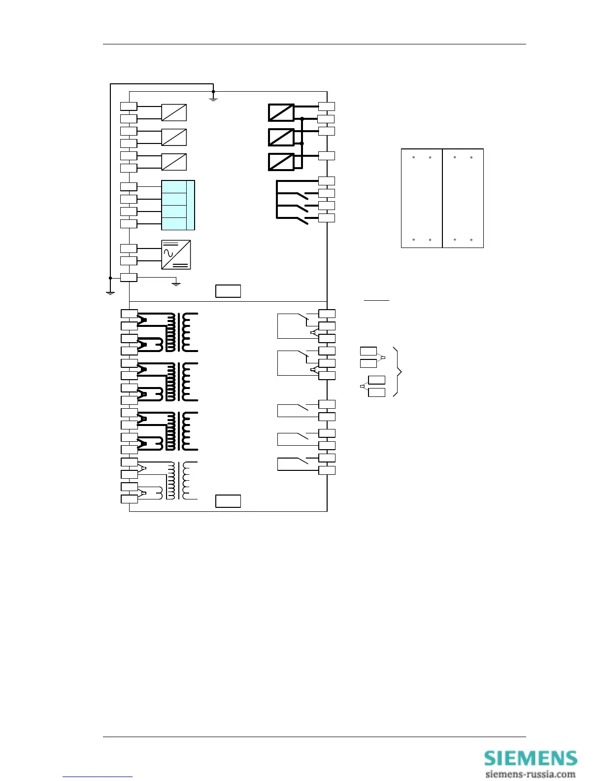
Shows contacts internal to relay case
assembly.
Contacts close when the relay chassis is
withdrawn from case
NOTES
BI = Binary Input
BO = Binary Output
Items shown in BOLD are ordering options
Rear View
Arrangement of terminals and modules
BI 4
+ve
3
BI 5
+ve
5
BI 6
+ve
-ve
7
1
BO 7
11
13
BO 8
15
9
BO 6
Figure 1-5 Connections Diagram for 7SR11 Relay

 Loading...


