7SR11 & 7SR12 Description Of Operation
©2012 Siemens Protection Devices Limited Chapter 1 Page 69 of 76
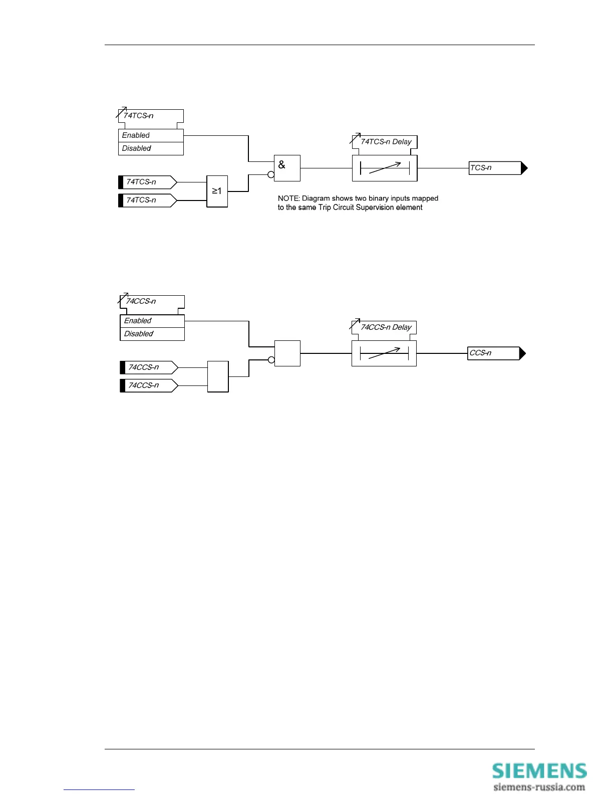
The use of one or two binary inputs mapped to the same Trip Circuit Supervision element (e.g. 74TCS-n) allows
the user to realise several alternative monitoring schemes.
Figure 4-10 Logic Diagram: Trip Circuit Supervision Feature (74TCS)
&
≥1
NOTE: Diagram shows two binary inputs mapped
to the same Close Circuit Supervision element
Figure 4-11 Logic Diagram: Close Circuit Supervision Feature (74CCS)

 Loading...


