7SR11 & 7SR12 Description Of Operation
©2012 Siemens Protection Devices Limited Chapter 1 Page 28 of 76
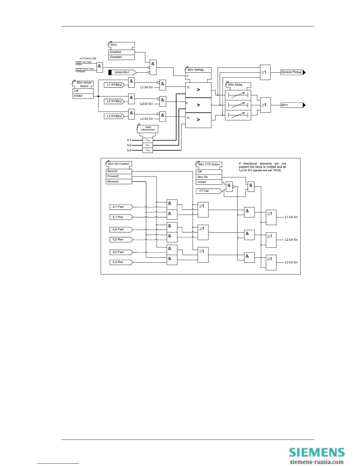
Figure 1-25 Logic Diagram: Instantaneous Over-current Element
3.1.3 Time Delayed Overcurrent Protection (51)
Two time delayed overcurrent elements are provided in the 7SR11 relay and four elements are provided in the
7SR12 relay.
51-1, 51-2, (51-3 & 51-4 – 7SR12)
51-n Setting sets the pick-up current level. Where the voltage controlled overcurrent function (51VCO) is used a
multiplier is applied to this setting where the voltage drops below the setting VCO Setting, see Section 3.2.
A number of shaped characteristics are provided. An inverse definite minimum time (IDMT) characteristic is
selected from IEC, ANSI or user specific curves using 51-n Char. A time multiplier is applied to the characteristic
curves using the 51-n Time Mult setting. Alternatively, a definite time lag delay (DTL) can be chosen using 51-n
Char. When Definite Time Lag (DTL) is selected the time multiplier is not applied and the 51-n Delay (DTL)
setting is used instead. The full list of operating curves is given in Chapter 2 – ‘Settings and Instruments Guide’.
Operating curve characteristics are illustrated in Chapter 3 – ‘Performance Specification’.
The 51-n Reset setting can apply a definite time delayed reset, or when the operation is configured as an IEC or
ANSI or user characteristic if the reset is selected as (IEC/ANSI) DECAYING reset the associated reset curve will
be used. The reset mode is significant where the characteristic has reset before issuing a trip output – see
‘Applications Guide’.

 Loading...


