7SR11 & 7SR12 Description Of Operation
©2012 Siemens Protection Devices Limited Chapter 1 Page 32 of 76
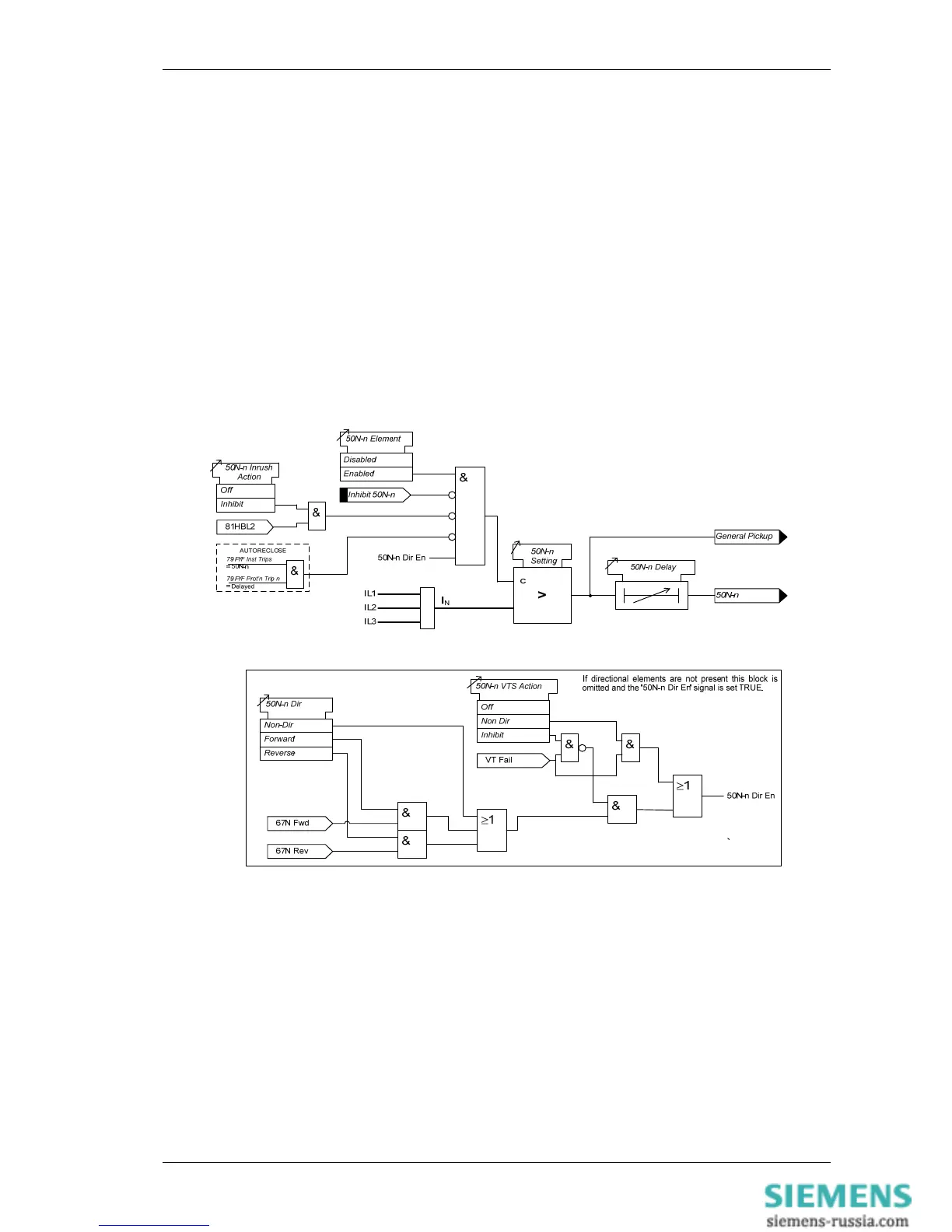
3.2.2 Instantaneous Derived Earth Fault Protection (50N)
Two instantaneous derived earth fault elements are provided in the 7SR11 relay and four elements are provided
in the 7SR12 relay.
50N-1, 50N-2, (50N-3 & 50N-4 – 7SR12)
Each instantaneous element has independent settings for pick-up current 50N-n Setting and a follower time
delay 50N-n Delay. The instantaneous elements have transient free operation.
Where directional elements are present the direction of operation can be set using 50N-n Dir. Control setting.
Directional logic is provided independently for each 50-n element.
Operation of the instantaneous earth fault elements can be inhibited from:
Inhibit 50N-n A binary or virtual input.
79 E/F Inst Trips: 50N-n When ‘delayed’ trips only are allowed in the auto-reclose sequence
(79 E/F Prot’n Trip n = Delayed).
50-n Inrush Action: Block Operation of the inrush current detector function.
50N-n VTSAction: Inhibit Operation of the VT Supervision function (7SR1205 & 7SR1206).
Figure 1-29 Logic Diagram: Derived Instantaneous Earth Fault Element
3.2.3 Time Delayed Derived Earth Fault Protection (51N)
Two time delayed derived earth fault elements are provided in the 7SR11 relay and four elements are provided in
the 7SR12 relay.
51N-1, 51N-2, (51N-3 & 51N-4 – 7SR12)
51N-n Setting sets the pick-up current level.
A number of shaped characteristics are provided. An inverse definite minimum time (IDMT) characteristic is
selected from IEC and ANSI curves using 51N-n Char. A time multiplier is applied to the characteristic curves
using the 51N-n Time Mult setting. Alternatively, a definite time lag delay (DTL) can be chosen using 51N-n

 Loading...


