7SR11 & 7SR12 Description Of Operation
©2012 Siemens Protection Devices Limited Chapter 1 Page 68 of 76
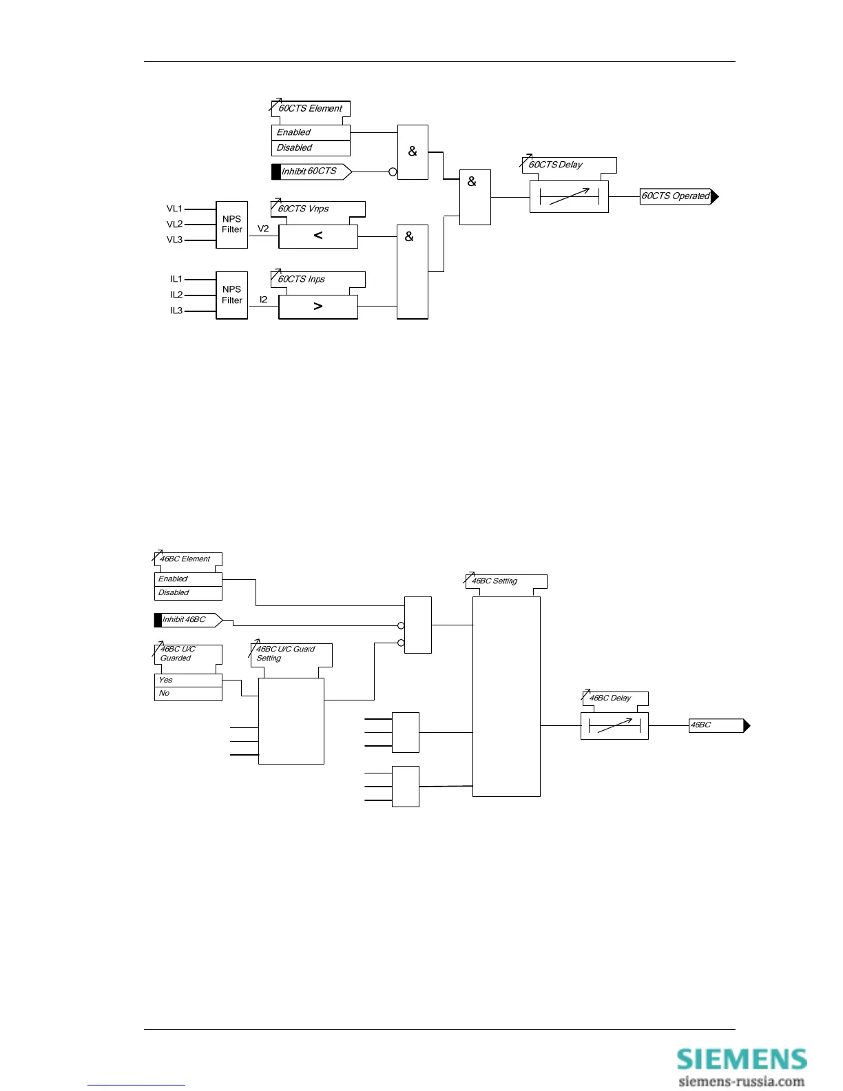
Figure 4-8 Logic Diagram: CT Supervision Function (60CTS) – 7SR12
5.4 Broken Conductor (46BC)
The element calculates the ratio of NPS to PPS currents. Where the NPS:PPS current ratio is above 46BC
Setting an output is given after the 46BC Delay.
The Broken Conductor function can be inhibited from
Inhibit 46BC A binary or virtual input.
46BC U/I Guard A minimum load current
c
&
IL1
IL2
IL3
NPS
Filter
I2
IL1
IL2
IL3
PPS
Filter
I1
C
IL1
IL2
IL3
Figure 4-9 Logic Diagram: Broken Conductor Function (46BC)
5.5 Trip/ Close Circuit Supervision (74TCS & 74CCS)
The relay provides three trip and three close circuit supervision elements, all elements are identical in operation
and independent from each other allowing 3 trip and 3 close circuits to be monitored.
One or more binary inputs can be mapped to 74TCS-n. The inputs are connected into the trip circuit such that at
least one input is energised when the trip circuit wiring is intact. If all mapped inputs become de-energised, due to
a break in the trip circuit wiring or loss of supply an output is given.
The 74TCS-n Delay setting prevents failure being incorrectly indicated during circuit breaker operation. This delay
should be greater than the operating time of the circuit breaker.

 Loading...


