7SR11 & 7SR12 Description Of Operation
©2012 Siemens Protection Devices Limited Chapter 1 Page 27 of 76
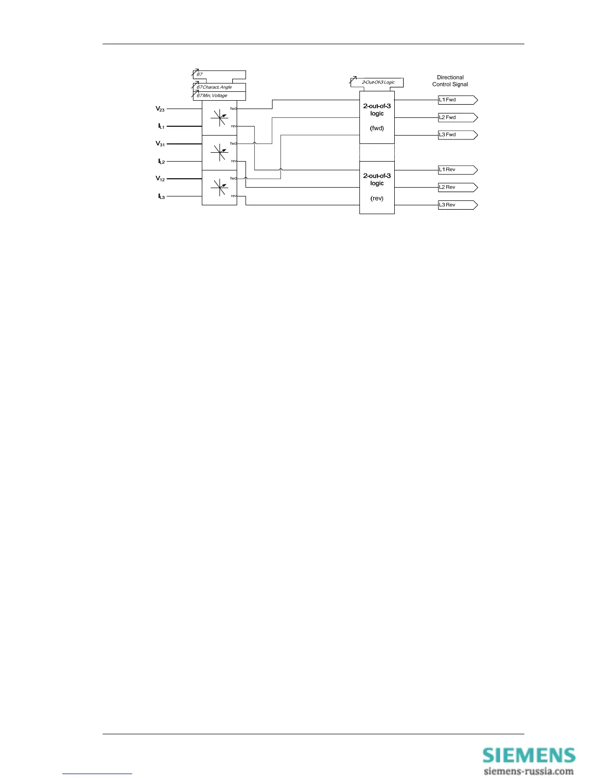
Figure 1-24 Logic Diagram: Directional Overcurrent Element (67)
3.1.2 Instantaneous Overcurrent Protection (50)
Two Instantaneous overcurrent elements are provided in the 7SR11 relay and four elements are provided in the
7SR12 relay.
50-1, 50-2, (50-3 & 50-4 – 7SR12)
Each instantaneous element (50-n) has independent settings. 50-n Setting for pick-up current and 50-n Delay
follower time delay. The instantaneous elements have transient free operation.
Where directional elements are present the direction of operation can be set using 50-n Dir. Control setting.
Directional logic is provided independently for each 50-n element, e.g. giving the option of using two elements set
to forward and two to reverse.
Operation of the instantaneous overcurrent elements can be inhibited from:
Inhibit 50-n A binary or virtual input.
79 P/F Inst Trips: 50-n When ‘delayed’ trips only are allowed in the auto-reclose sequence
(79 P/F Prot’n Trip n = Delayed).
50-n Inrush Action: Block Operation of the inrush current detector function.
50-n VTS Action: Inhibit Operation of the VT Supervision function (7SR1205 & 7SR1206).

 Loading...


