7SR11 & 7SR12 Description Of Operation
©2012 Siemens Protection Devices Limited Chapter 1 Page 33 of 76
Char. When definite time lag (DTL) is selected the time multiplier is not applied and the 51N-n Delay (DTL)
setting is used instead.
The 51-n Reset setting can apply a definite time delayed reset, or when the operation is configured as an IEC or
ANSI or user characteristic if the reset is selected as IEC/ANSI (DECAYING) reset the associated reset curve will
be used. The reset mode is significant where the characteristic has reset before issuing a trip output – see
‘Applications Guide’
A minimum operate time for the characteristic can be set using the 51N-n Min. Operate Time setting.
A fixed additional operate time can be added to the characteristic using the 51N-n Follower DTL setting.
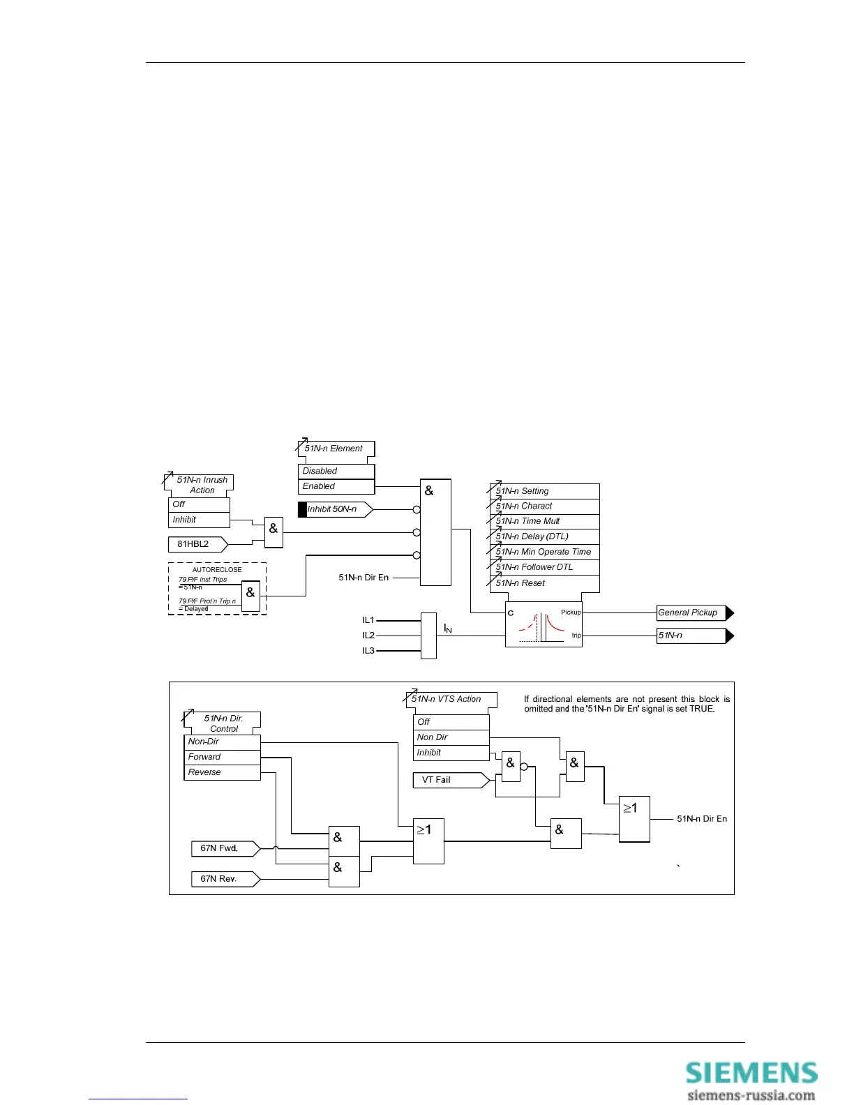
Where directional elements are present the direction of operation can be set using 51N-n Dir. Control setting.
Directional logic is provided independently for each 51N-n element.
Operation of the time delayed earth fault elements can be inhibited from:
Inhibit 51N-n A binary or virtual input.
79 E/F Inst Trips: 51N-n When ‘delayed’ trips only are allowed in the auto-reclose sequence
(79 E/F Prot’n Trip n = Delayed).
50-n Inrush Action: Block Operation of the inrush current detector function.
51N-n VTSAction: Inhibit Operation of the VT Supervision function (7SR1205 & 7SR1206).
Figure 1-30 Logic Diagram: Derived Time Delayed Earth Fault Protection

 Loading...


