7SR11 & 7SR12 Description Of Operation
©2012 Siemens Protection Devices Limited Chapter 1 Page 50 of 76
It should be noted that neutral voltage displacement can only be applied to VT arrangements that allow zero
sequence flux to flow in the core i.e. a 5-limb VT or 3 single phase VTs. The VT primary winding neutral must be
earthed to allow the flow of zero sequence current.
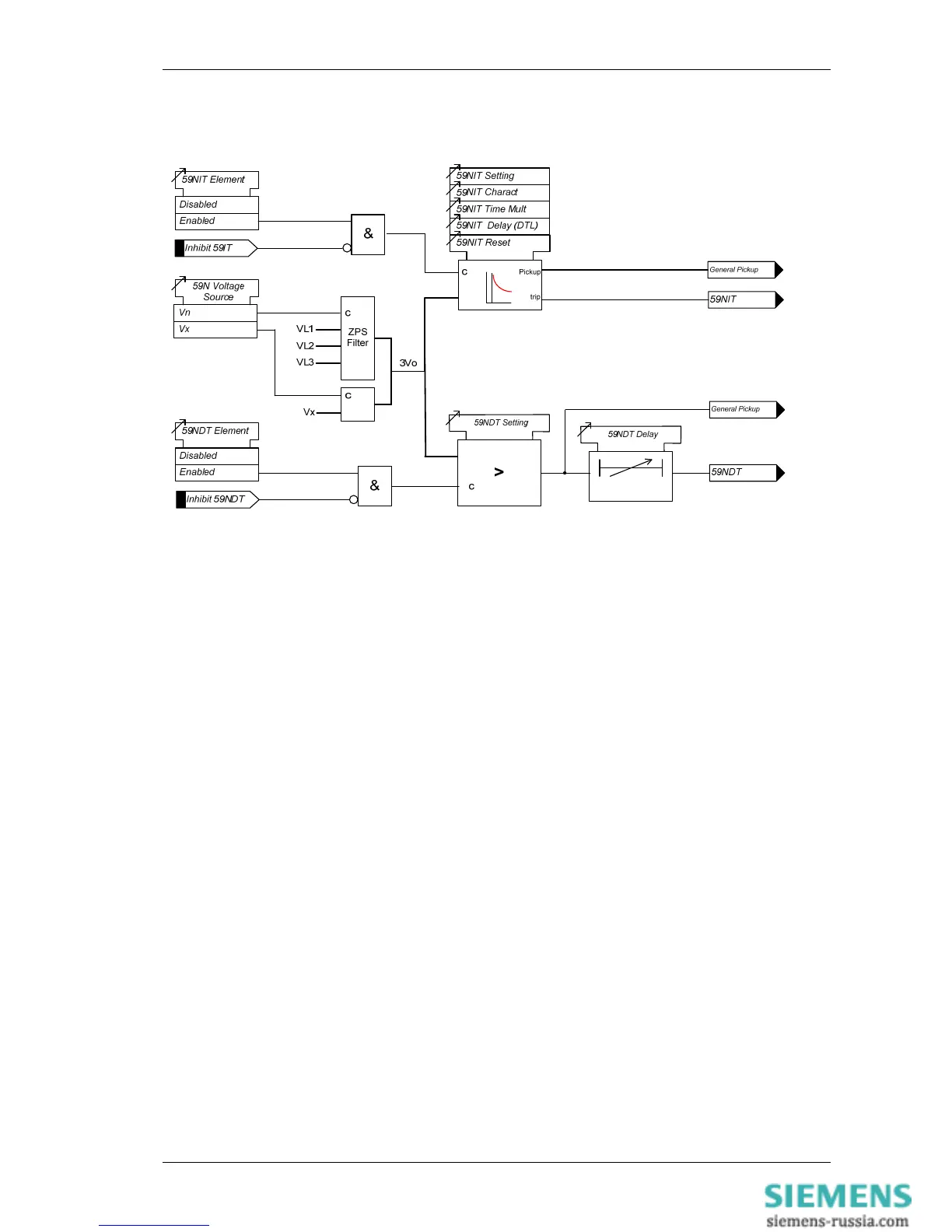
Figure 1-51
Logic Diagram: Neutral Overvoltage Element (59N)
3.14 Voltage Protection: Under/Over Frequency (81) – 7SR12
Four under/over frequency elements are provided in the 7SR12 relay – 81-1, 81-2, 81-3 & 81-4.
The relay utilises fundamental voltage measurement values for this function. The frequency calculation is based
on the highest input voltage derived from the voltage selection algorithm.
Frequency elements are blocked if all phase voltages fall below the 81 U/V Guard setting.
The sense of the element (under-frequency or over-frequency) is set by the 81-n Operation setting.
81-n Setting sets the pick-up voltage level for the element.
An output is given after elapse of the 81-n Delay setting.
The 81-n Hysteresis setting allows the user to vary the pick-up/drop-off ratio for the element.
Operation of the under/over frequency elements can be inhibited from:
Inhibit 81-n A binary or virtual input, or function key.
81-n U/V Guarded Under voltage guard element.

 Loading...


