7SR11 & 7SR12 Description Of Operation
©2012 Siemens Protection Devices Limited Chapter 1 Page 15 of 76
Section 2: Hardware Description
2.1 General
The structure of the relay is based upon the Reyrolle Compact hardware platform. The relays are supplied in a
size E4 case (where 1 x E = width of approx. 26mm). The hardware design provides commonality between
products and components across the Reyrolle Compact range of relays.
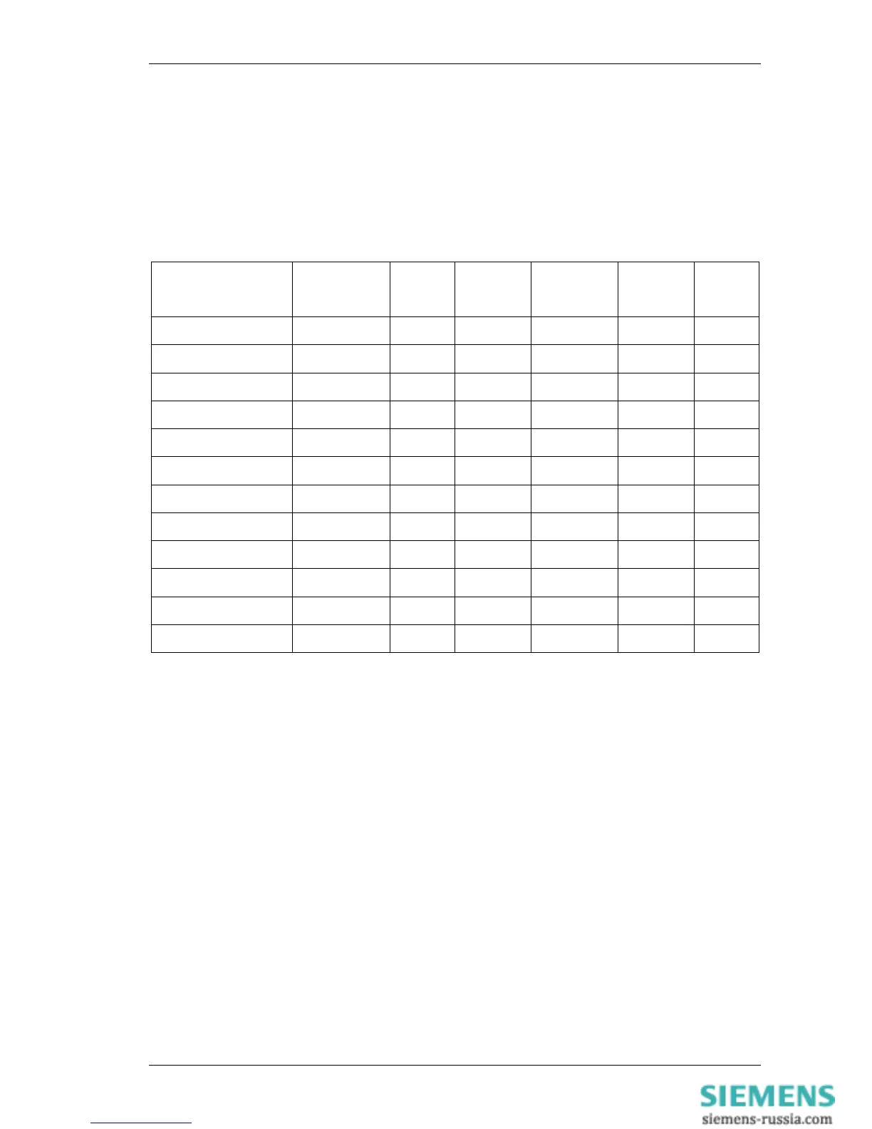
Table 1-3 Summary of 7SR1 Relay Configurations
Relay Current
Inputs
SEF
Inputs
Voltage
Inputs
Binary
Inputs
Binary
Outputs
LEDs
7SR1101-1 1 0 0 3 5 10
7SR1101-3 1 1 0 3 5 10
7SR1102-1 4 0 0 3 5 10
7SR1102-3 4 1 0 3 5 10
7SR1103-1 4 0 0 6 8 10
7SR1103-3 4 1 0 6 8 10
7SR1204-2 1 0 3 3 5 10
7SR1204-4 1 1 3 3 5 10
7SR1205-2 4 0 3 3 5 10
7SR1205-4 4 1 3 3 5 10
7SR1206-2 4 0 3 6 8 10
7SR1206-4 4 1 3 6 8 10
Relays are assembled from the following modules:
1) Front Fascia with 9 configurable LEDs and 1 Relay Healthy LED.
2) Processor module.
3) Current Analogue / Output module
1 x Current + 5 x Binary Outputs (BO)
4 x Current + 5 x Binary Outputs (BO)
4) Voltage Analogue / Input / output module
3 x Voltage + 3 x Binary Input and 3 x Binary Output Module. (7SR12)
3 x Binary Input (BI) and 3 x Binary Output (BO) Module.
5) Power Supply and 3 x Binary Input (BI) and RS485.
2.2 Case
The relays are housed in cases designed to fit directly into standard panel racks. The case has a width of 104mm
and a height of 177 mm (4U). The required panel depth (with wiring clearance) is 242 mm.
The complete relay assembly is withdrawable from the front of the case. Contacts in the case ensure that the CT
circuits and normally closed contacts remain short-circuited when the relay is removed. To withdraw the relay,
remove the plastic fascia cover by rotating the two securing pins and withdraw using the plastic handles. The
relay should not be carried using these handles. The relay should only be held by the top and bottom plates and
the user should not touch the exposed PCB’s.

 Loading...


