7SR11 & 7SR12 Description Of Operation
©2012 Siemens Protection Devices Limited Chapter 1 Page 46 of 76
100%
I
I
θ
2
θ
2
F
×=
Where: θF = final thermal state before disconnection of device
49 Overload Setting I
θ
is expressed as a multiple of the relay nominal current and is equivalent to the factor k.
IB
as defined in the IEC255-8 thermal operating characteristics. It is the value of current above which 100% of
thermal capacity will be reached after a period of time and it is therefore normally set slightly above the full load
current of the protected device.
The thermal state may be reset from the fascia or externally via a binary input.
Thermal overload protection can be inhibited from:
Inhibit 49 A binary or virtual input.
c
cap alarm
trip
cap alarm
trip
cap alarm
trip
&
1
1
r
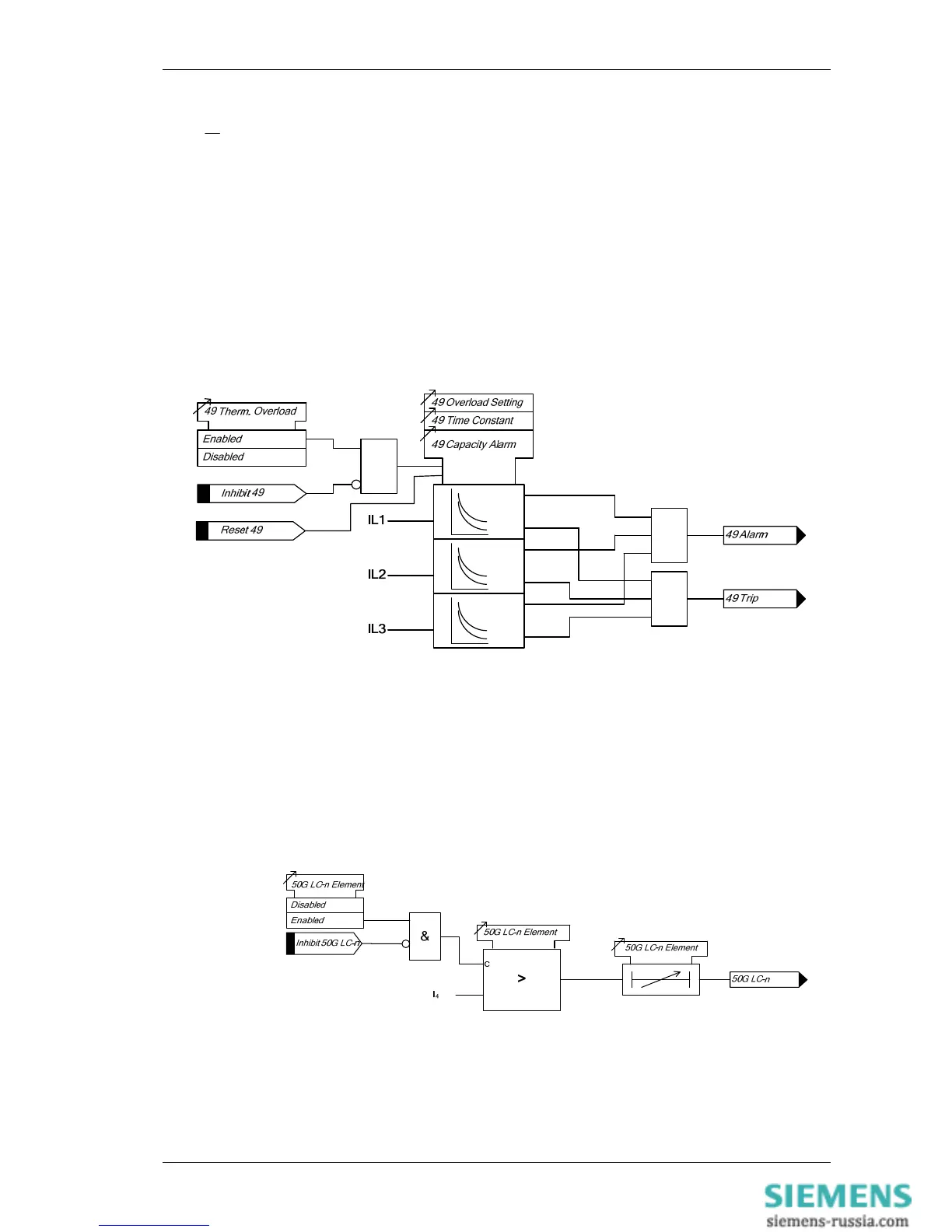
Figure 1-45 Logic Diagram: Thermal Overload Protection (49)
3.10 Current Protection: Line Check 50LC, 50G LC and 50SEF
LC – Only software option ‘C’
If a fault appears on the line during the Close Pulse. This prevents a CB being repeatedly closed onto
a faulted line. A line check element is provided for phase, earth and sensitive earth fault elements.
In total two line check elements are provided -1, & -2.
Figure 1-46 Logic Diagram: 50G Line Check Elements (50G LC)

 Loading...


