Instrument Description
2ndHarm. Current
1
I
a
0.000A
I
b
0.000A
I
c
0.000A
Displays the second harmonics values of I
a
, I
b
, I
c
phase currents.
THERMAL METER
→ to view
Thermal meter displays the status of equipment thermal level.
TEST/RESET▶ key allows you to access the subgroup
Thermal Capacity
θ 0.0%
Displays the thermal level of the protected equipment.
The value of thermal capacity refreshes at every 1 s interval.
BINARY I/P METER
→ to view
Binary input meter displays the status of the binary input signals.
The TEST/RESET▶ key allows you to access the subgroup.
The value of binary input status refreshes at every 1 s interval.
BI 1-4
_ _ _ _
Displays the state of the binary inputs 1 to 4 (Depending on the
model, the number of binary inputs varies).
If the status is _, the value is 0. If the status is 1, the value is 1.
BINARY O/P METER
→ to view
Binary output meter displays the status of the binary output
signals.
TEST/RESET▶ key allows you to access the subgroup.
The value of BO status refreshes at every 1 s interval.
BO 1-4
_ _ _ _
Displays the state of the binary outputs 1 to 4 (Depending on the
model, the number of binary outputs varies).
If the status is _, the value is 0. If status is 1, the value is 1.
GEN ALARM METER
→ to view
The general alarm meter displays the status of the general
alarms.
The TEST/RESET▶ key allows you to access the subgroup.
The general alarm status refreshes at every 1 s interval.
ALARM1 Cleared
ALARM2 Cleared
ALARM3 Cleared
ALARM4 Cleared
Displays the state of general alarms 1 to 4.
The alarm can be renamed in the settings menu and the updated
name appears in this window.
The status can be Cleared or Raised depending on the binary
input linked to the general alarm.
MISC METER The Misc. meter gives more information about the active settings
group, fault, and event records in the device, status of auxiliary
input and IRF.
For more information about IRF, refer to Self monitoring.
BATTERY PROFILE The battery profile meter displays the status of the operations
performed on the battery power.
Fault Data Mode
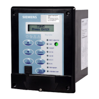
The 7SR45 Argus Relay stores a maximum of 10 fault records. Each stored fault data can be viewed by pressing
the TEST/RESET▶ key. Each record contains data of the operated elements, analog values, and LED status at
the time of the fault. The data is viewed by scrolling down using the ▼ key.
NOTE
The phase LEDs do not glow when the trip is caused by the 49 function.
The LCD does not display phase information when the trip is caused by the 49 function.
4.5.5
1
Not available in the 7SR450[1/3]-xGA10-1AA0 variant.
Using the Relay Fascia
4.5 Structure of the Menu
54 Reyrolle, Operating, Manual
C53000-B7040-C101-1, Edition 08.2020



 To Next Page