Do you have a question about the Siemens 7VK512 and is the answer not in the manual?
Describes the application of the numerical auto-reclosure relay.
Lists the key features and capabilities of the 7VK512 relay.
Details the auto-reclosure and synchronism/voltage check functions.
Explains the housing arrangements for panel surface and flush mounting.
Provides detailed physical dimensions for different housing types.
Specifies the coding system for ordering different relay configurations.
Presents general electrical and mechanical specifications.
Details parameters and times related to the auto-reclosure function.
Explains settings for synchronism and voltage check functions.
Describes additional functions like fault recording and monitoring.
Overviews the hardware structure and basic operation of the relay.
Explains the automatic reclosure function, its types, and logic.
Details the operation of synchronism and voltage check functions.
Describes the operation of functions like fault recording and monitoring.
Instructions for handling and unpacking the device safely.
General preparations and precautions before installation.
Guides on mounting the device in different housing types.
How to verify the device's rated data for installation.
Explains how to check control voltages for binary inputs.
Details on connecting binary inputs and outputs and general diagrams.
Steps to verify all connections after installation.
How to configure the device's operational functions.
Outlines preconditions for operational configuration.
Details on setting operating parameters via address block 70.
Explains how to configure various device functions.
Introduction to device function configuration.
How to program the scope of functions using address block 78.
Explains marshalling of inputs, outputs, and LEDs.
Introduction to marshalling of binary inputs, outputs, and LEDs.
Details on marshalling binary inputs via address block 61.
Explains marshalling of signal outputs/alarm relays (address block 62).
Details on marshalling LED indicators via address block 63.
Explains marshalling of command/trip relays (address block 64).
Configuration for substation automation communication.
General safety warnings for operating the relay.
How to interact with the relay using its interface.
Description of the relay's keyboard and display.
How to operate the relay using a PC.
Preconditions required for relay operation.
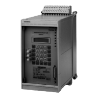
Visual representation of the relay's front panel layout.
General guidance on setting functional parameters.
Introduction to setting functional parameters.
Information on using selectable parameter sets.
Procedure for setting the device's date and time.
How initial displays appear and their meaning.
Details on power system data configuration.
Configuration for fault recording parameters.
Configuration settings for the auto-reclose function.
Configuration settings for synchronism and voltage check.
Guidance on performing routine checks on the relay.
Instructions for replacing the clock module.
Procedures for tracing faults within the device.
Contains general wiring and connection diagrams for the relay.
Detailed connection diagrams for different configurations.
Reference tables for parameters and functions.
| Frequency | 50/60 Hz |
|---|---|
| Rated voltage | 24-250 V AC/DC |
| Current transformer input | 1 A or 5 A |
| Rated current | 5 A |
| Operating voltage | 24-250 V AC/DC |
| Number of contacts | 4 |
| Contact rating | 5 A |
| Protection class | IP20 |