8PQ9801-8AA56 9
Hauptsammelschienensystem mit
A) Die Verbindungsschrauben für
- L1, L2, L3 M10x45 (8PQ4000-1AA67)
- N/PEN - 1 Teilleiter M10x35 (8PQ4000-2AA68)
- N/PEN - 2 Teilleiter M10x45 (8PQ4000-1AA67)
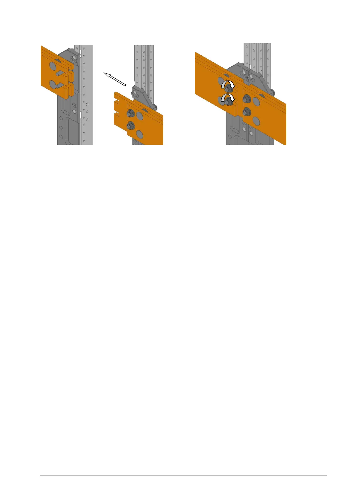
sind in die HSS des linken Feldes einzubringen (step 1).
B) Fetten der Kontaktflächen mit Vaseline.
C) Das anzureihende Feld an die bereits befestigten Felder heran
schieben, bis deren Laschen fast die gegenüberliegenden
Teilleiter berühren. Die Höhenlage der Laschen ist vom Hersteller
ausgerichtet. Werden Abweichungen festgestellt, die das
Schieben der Laschen auf die Schrauben behindern, diese bitte
bauseitig ausrichten. Wird hierzu die Verschraubung der Laschen
gelöst, so sind diese danach mit dem angegebenen Drehmoment
wieder anzuziehen. Die Feldfronten bündig ausrichten und das
anzureihende Feld heran schieben bis die Rahmen sich berühren.
D) Die Schrauben M6 aus dem Beipack können benutzt werden, um
das linke und rechte Feld zusammenzuziehen. Dazu werden sie
in den Lochungen der Gerüstholme eingesetzt. Bitte beachten Sie
hierzu Abschnitt 2.
E) Bei der Variante mit 2 Teilleitern je Phase die Spannscheiben und
Muttern M10 aus dem Beipack wie oben gezeigt in das
“Werkzeug zur Sammelschienenverschraubung“ einlegen. Die
Muttern zwei bis drei Umdrehungen auf die Schraubenenden
drehen. Dann das Spezialwerkzeug abziehen, damit die Krallen
nicht eingeklemmt werden.
F) Mit Drehmomentschlüssel, Verlängerung (mit fester Nuss) ggf.
Kardangelenk mit zusätzlicher Verlängerung das Solldrehmoment
von 40Nm aufbringen (step 3).
A) The connecting bolts
- L1, L2, L3 M10x45 (8PQ4000-1AA67)
- N/PEN - 1 conductor M10x35 (8PQ4000-2AA68)
- N/PEN - 2 conductors M10x45 (8PQ4000-1AA67)
must be mounted in the main busbar of the left section
(step 1).
B) Contact surfaces must be greased with Vaseline.
C) Push the sections to be aligned against the fixed section, until
the fishplates for screw fastening almost touch the opposite
conductor. The vertical height of the fishplates has been
already aligned by the manufacturer. In case of any deviations
that handicap shifting the fishplates onto the bolts, please
adjust the fishplates on site. Boltings, which have been
unfastened for this purpose, shall be tightened subsequently
with correct torque. Align the section fronts and push the
additional section(s) towards the fixed ones until the
frameworks touch one another.
D) The M6 bolts of the enclosure may be used to pull the frame of
the left- and right-hand section together. For this purpose, they
shall be inserted into the holes of the top frame profile. Please,
observe chapter 2.
E) For the version with 2 conductors per phase, put the conical
spring washers and hexagonal nuts from the accessories as
shown above into the “tool for main busbar bolting“. Turn the
nuts two to three revolutions onto the thread of the bolts. Then
extract the special tool off to avoid jamming of the claws.
F) Apply 40 Nm of torque using a torque wrench, socket spanner
inserts (with fixed nut), if necessary, use a cardan joint and
additional extension (step 3).
40Nm
 Loading...