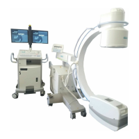
ARCADIS Orbic Quick Guide
3D option
71
3D view
In the 3D task card, a series (range) of two-
dimensional slice images is reconstructed
from the scanned 3D volume (MPR = [Multi-
planar Reconstruction] display mode).
3D task card
The MPR series is displayed in the reference
segments in the three standard views. The
colored reference lines indicate the position
and viewing direction (see arrows) of the cut
planes in the two other reference segments.
(1) Reference segment (sagittal view)
(2) Reference segment (coronal view)
(3) Reference segment (transversal view)
(4) Output segment for newly reconstructed
images and series
(5) Control area for image view/orientation,
display mode, range calculation, output
control
Changing the standard view
✧ Click a reference segment.
✧ Select the desired view for the segment
in the Orientation subtask card (6).