22 Installing the WLAN Expansion
DRAFT 22.04.2008
ARCADIS SP00-000.814.09.01.02 Siemens
11.07 CS PS SP
Page 22 of 78
Medical Solutions
• Place the two end pieces (5/Fig.4/p.14) to secure the power supply on the cap rail
and secure them in place.
¹ The power supply is secured against moving sideways on the cap rail.
Cabling the WLAN Client
Wiring of the 24V Cable on the WLAN Power Supply
• Wire the 24V connection lead on the WLAN power supply.
¹ Connect the L1+ cable end to the power supply + terminal. See (4/Fig. 15 / p. 22).
¹ Connect the M1 cable end to the power supply - terminal. See (5/Fig. 15 / p. 22).
Wiring of the 24V Cable on the WLAN Client
• Wire the 24V connection lead from the WLAN power supply to the WLAN Client.
NOTE
The WLAN Client is shipped with a 4-pole coupling to con-
nect the DC voltage power supply. To wire the coupling,
unplug it from the WLAN Client "DC24V 0.25A" socket. The
cable terminals for the coupling will then be accessible.
¹ Connect the L1+ cable end to the L1+ coupling. See (3/Fig. 15 / p. 22).
¹ Connect the M1 cable end to the M1 coupling. See (2/Fig. 15 / p. 22).
¹ Plug the coupling back into the "DC24V 0.25A" socket on the WLAN Client. The
plug-in connection is designed so that the poling is always correct.
Installing the WLAN Power Supply
• Remove the small side cover panel. See (Fig. 14 / p. 22).
• Break out the left perforated metal section from the cover panel.
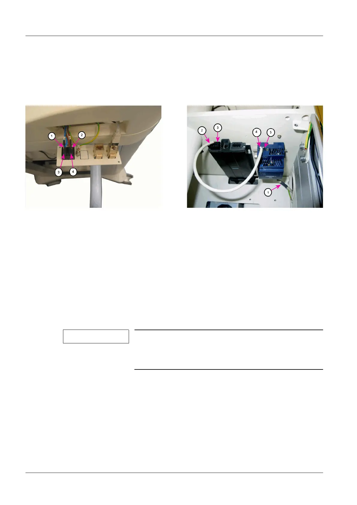
Fig. 14: WLAN power switch
Pos. 1 WLAN power supply cable, S15.1A power switch
Pos. 2 WLAN power supply cable, S15.2A power switch
Pos. 3 Power outlet strip cable - S15.1 power switch
Pos. 4 Power outlet strip cable - S15.2 power switch
Fig. 15: WLAN Client wiring
Pos. 1 WLAN power supply cable - WLAN power switch
Pos. 2 24V WLAN power supply cable - WLAN Client
Pos. 3 24V power supply coupling WLAN Client
Pos. 4 WLAN Client 24V+ terminal
Pos. 5 WLAN Client 24V- terminal
 Loading...