Operating terminals
4
A6V10430571_en--_c 21 | 57
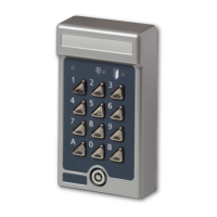
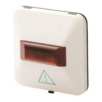
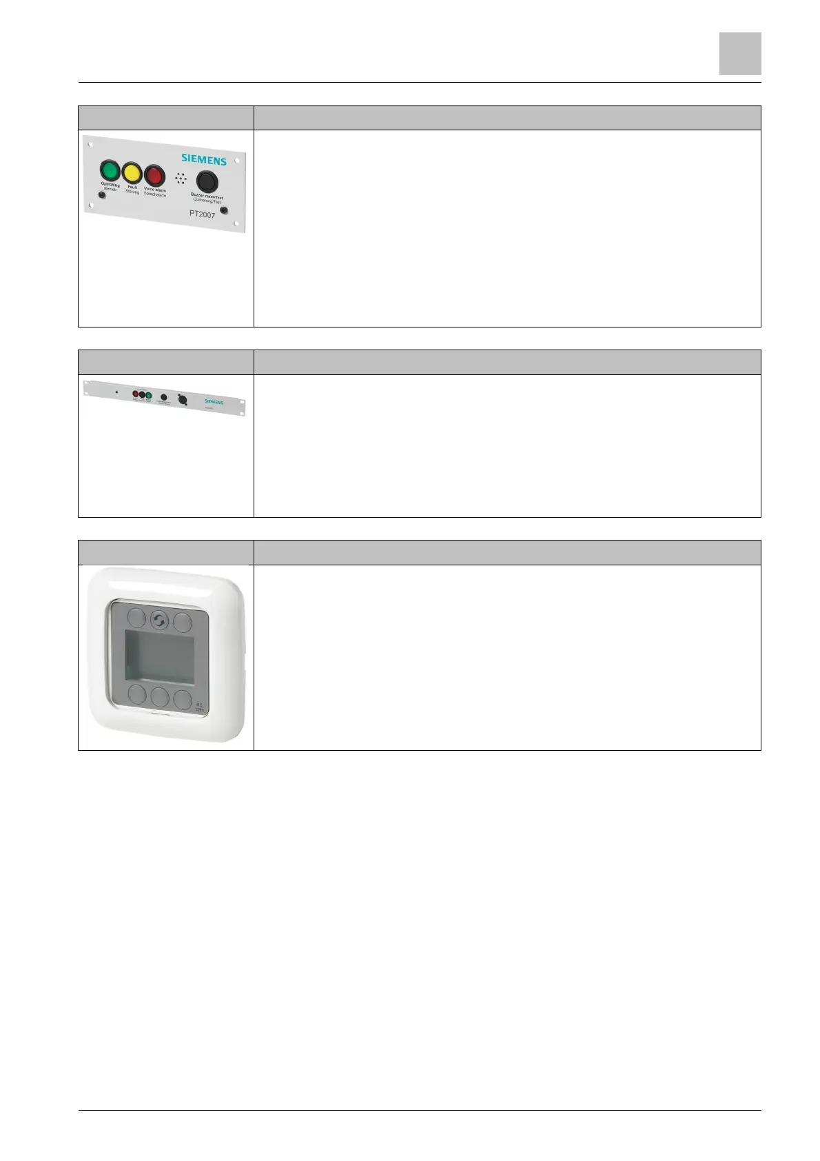
PT2007-A1 'System state indicator (door)'
● EN 54-16-compliant indicator panel for visual and acoustic status
messages
● Color-coded visual indicators: operation, fault, and alarm
– Operation: green
– Fault: yellow
– Voice Alarm: red
● Fault warning with acoustic warning signal
● Acknowledge acoustic warning and LED test: black button
● Potential-free fault contact
● Design: open frame
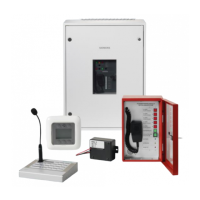
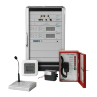
PT2005-A1 'Alarm control panel (19")'
● Activation of voice alarms
– Activate: red LED button
– Reset: black button
– Silence: green LED button
● Button to acknowledge faults: black
● Service socket
● Design: 19", 1 HU
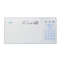
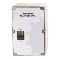
PT2006-A1 'Remote control panel'
● Buttons and display for channel selection
● Sound level settings
● Connection of up to 16 remote control panels to the digital audio matrices
PC2001-A1, PC2002-A1, PC2003-A1, PC2005-A1, or PC2006-A1 possible
via the RS485 interface
● Supplied with installation frame
● For installation in recessed box
● 4-pin cables for RS485 interface and power supply