Operating elements in the system
Operating terminals
4
20 | 57 A6V10430571_en--_c
4.2 Operating terminals
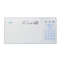
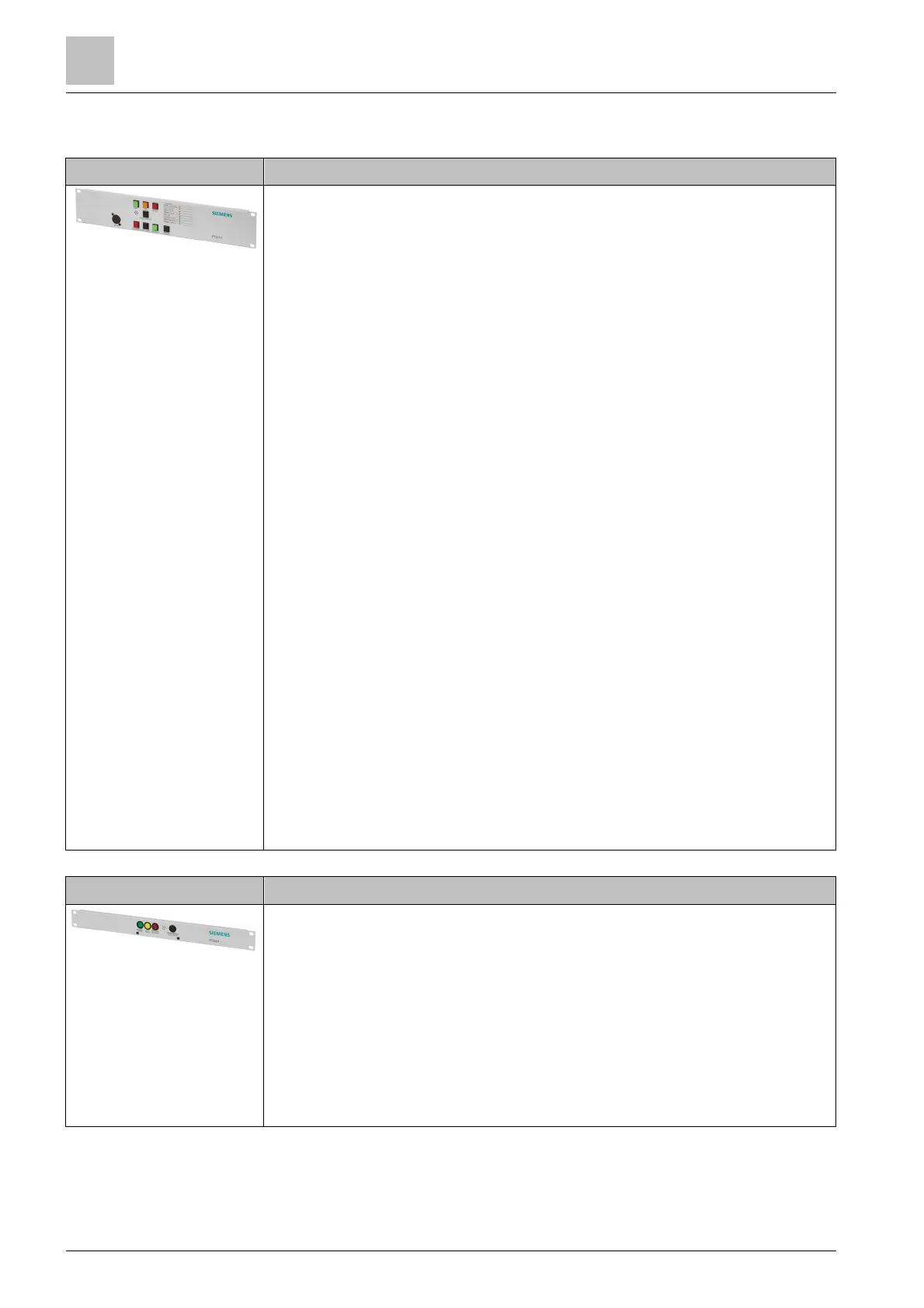
PT2010-A1 'System operating unit (19")'
● EN 54-16-compliant indicator panel for visual and acoustic status
messages and control voice alarms
● Display of system status
● Control of voice alarms
● Fault warning with acoustic warning signal
● Color-coded visual indicators: operation, fault, and alarm
– Operation: green
– Fault: yellow
– Voice Alarm: red
● Color-coded control buttons: control of voice alarms, acknowledges
– <Start Voice Alarm>: red LED indicator button
– <Reset Voice Alarm>: black button
– <Silence Voice Alarm>: green LED indicator button
– Acknowledge faults: black button
– Acknowledge acoustic warning and LED test: black button
● 8 predefined visual fault indicators: yellow
– Power fault
– Fuse fault
– Earth fault
– 'PACE-Net' fault
– 'PACE-Bus' fault
– Amplifier fault
– Microphone fault
– Speaker circuit fault
● 8 user-configurable state indicators: yellow
● Potential-free fault contact
● Service socket
● RS485 data transmission ('PACE-Bus')
● Addressable via 4-way SIP switch for 'PACE-Bus' connection
● Design: 19", 2 HU
PT2004-A1 'System state indicator (19")'
● EN 54-16-compliant indicator panel for visual and acoustic status
messages
● Color-coded visual indicators: operation, fault, and alarm
– Operation: green
– Fault: yellow
– Voice Alarm: red
● Fault warning with acoustic warning signal
● Acknowledge acoustic warning and LED test: black button
● Potential-free fault contact
● Design: 19", 1 HU