Installation, connecting up and commissioning
5.2 Installing the CP, connecting power and ground
CP 343-1
38 Manual, 12/2018, C79000−G8976−C201-08
Attachment to Industrial Ethernet (PROFINET interface): 2 x 8pin RJ45 jack
Connecting the power supply
Slider for setting the chassis ground connection
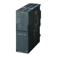
Figure 5-1 Connectors of the CP
Ground/chassis ground concept
Note
Note the instructions regarding the grounding and chassis ground concept in the
SIMATIC
S7 installation guides; see “SIMATIC S7 Programmable Controller S7300 -
Installation and Hardware: Installation Manual":
/12/ (Page 74)".
Behind the hinged panel on the left of the device, you will see a slider with which you can
connect or disconnect the chassis ground of the 24V power supply with reference ground.
● Slider pushed in: Chassis ground and reference ground are connected (caution: you can
feel the slider lock into position).
● Slider pulled out: There is no connection between chassis ground and reference ground.
When shipped: Slider pushed in
Use a screwdriver to set the slider.
 Loading...
