CP 343-1
Manual, 12/2018, C79000−G8976−C201-08
31
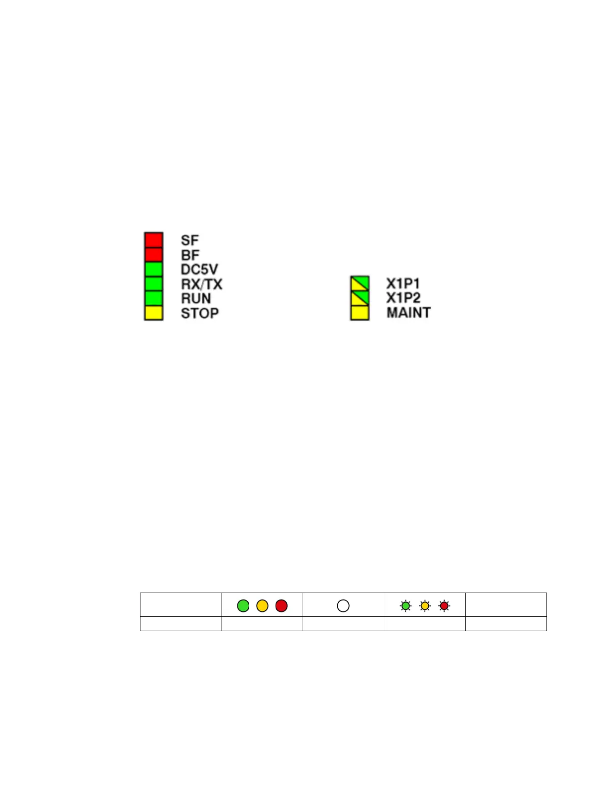
The display on the front panel consists of the following LEDs that indicate the operating
mode and communications status.
Figure 4-1 LEDs of the CP 343-1
The LEDs have the following meaning:
● SF: Group error
● BF: Bus fault on Ethernet interface
● DC5V: 5 VDC power supply via the backplane bus (green = OK)
● RX/TX: Acyclic data traffic, for example SEND/RECEIVE
(not relevant for PROFINET IO data)
● RUN: RUN mode
● STOP: STOP mode
● X1P1: Link status / activity of Ethernet port 1
● X1P2: Link status / activity of Ethernet port 2
● MAINT: Maintenance required (note/evaluate diagnostics buffer)
Legend for the following LED tables
-
ON OFF Flashing any
LEDs for displaying the operating mode
The different combinations of the LEDs on the front panel indicate the status:

 Loading...