27
There are two key-shaped cutouts on the top of the backbox. Make sure the end with the
two key-shaped cutouts is on top when installing the backbox.
The front door can be removed from the enclosure for more convenient installation.
Drill the two holes located in the previous step and screw in the top bolts, leaving a small gap
between the wall and each top bolt.
Place the backbox over the two top bolts and allow it to slide down over the bolts.
Mark, drill, and install the two bottom bolts in the backbox.
Tighten all four bolts securely against the back wall of the backbox.
If a semi-flush mount installation is desired, use the Semi-flush Trim for the FC2005. The
backbox can be mounted up to 3 1/2 inches into the wall. Place the semi-flush trim around the
backbox and affix to the wall with four #10 x 3/4 inch wood screws (provided with trim).
The screw type and length must be able to support the control panel, options and battery
set. You may need a different screw type, depending on the wall material.
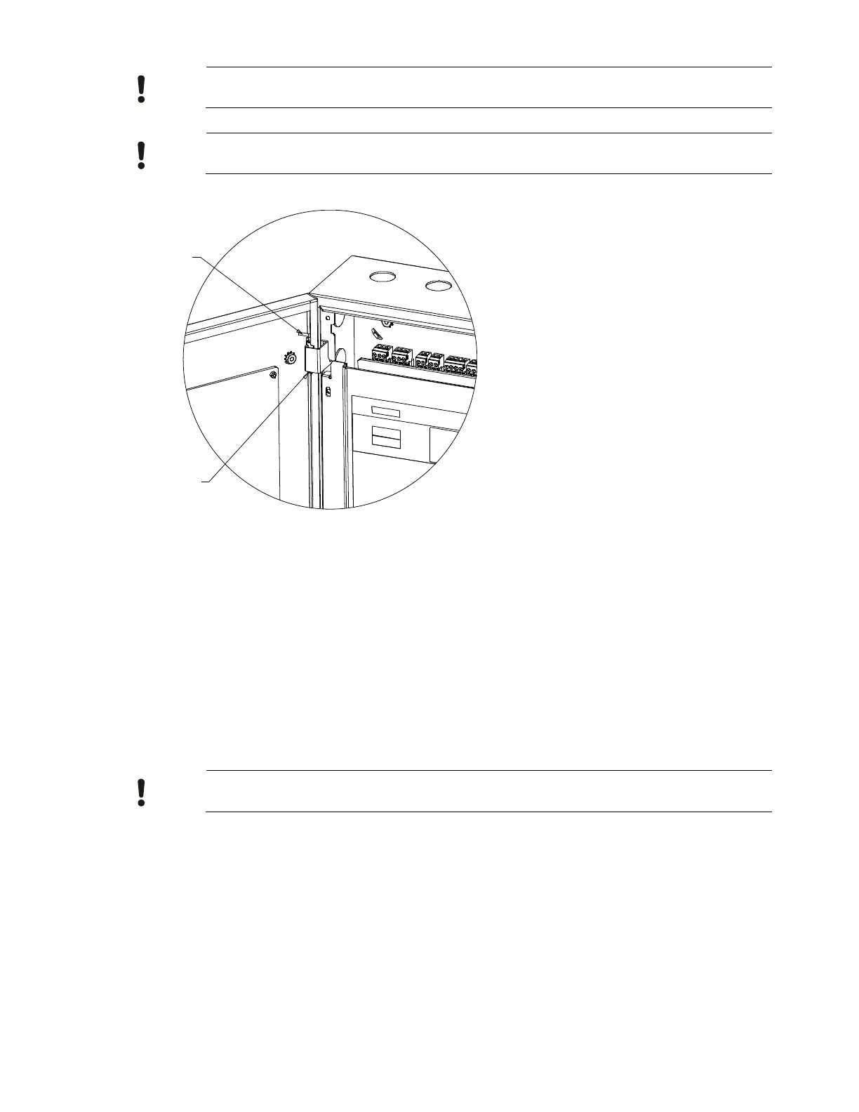
2. Hinge axis can
be removed
1. Remove the hinge
axis lock pin