42
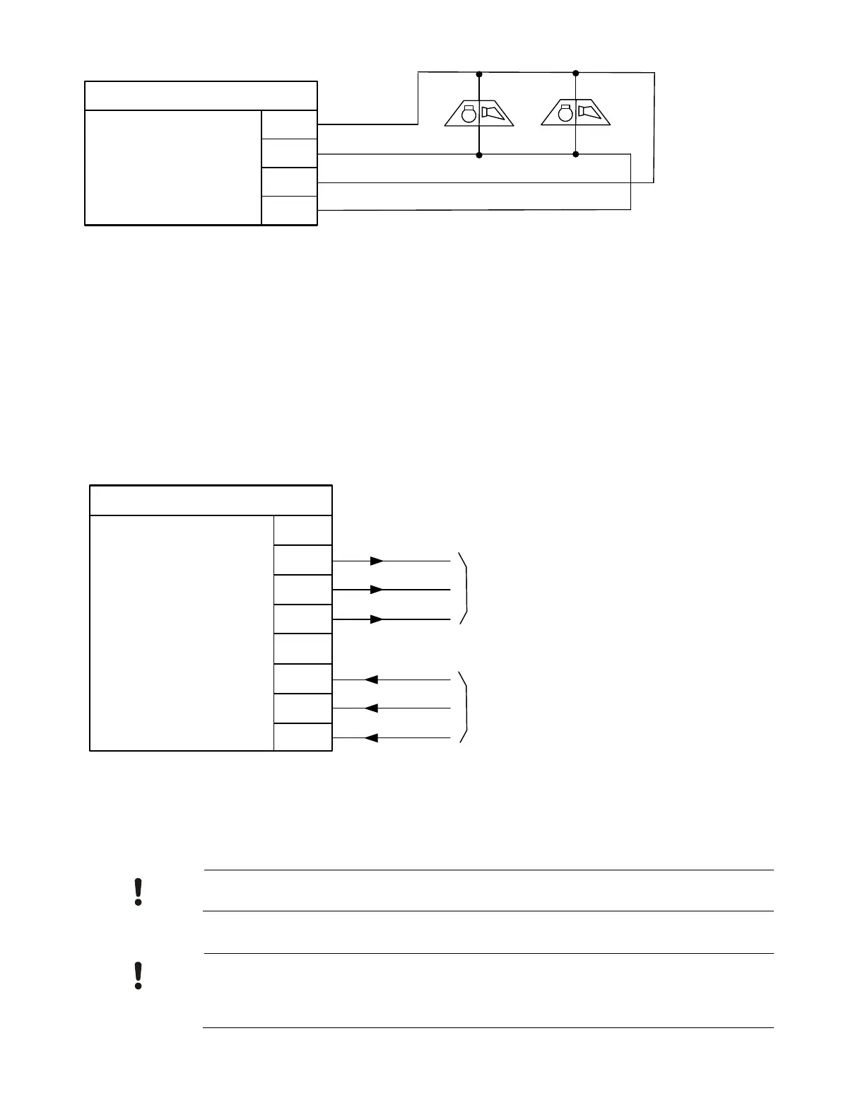
Serial Interface Circuit (UFP)
The serial interface circuit can address up to 8 devices, which includes annunciators and
printers. Up to 2 printers can be addressed. Devices on the circuit may be connected up to
4000 feet from the control panel.
Serial Interface Circuit (UFP)
(PR_A, PR_B) RS-485 level
Wire type - Twisted pair for data
EARTH – Shielding earth connection
Wire resistance - 50 Ohm/line (Max. 4000’)
Supervised, Power limited.
GND1
PR_A
PR_B
Serial interface circuit (UFP)
EARTH
Primary part
(X5)
GND1
SE_A
SE_B
EARTH
Secondary part
(X6)
Remote Device Power – The on-board auxiliary power can provide power for ONLY one
annunciator. If more power is required for the connected devices, external power must be
provided. Each address on the circuit must be fully powered from either auxiliary power of
control panel or external power.
If the annunciator is connected to a separate Power Supply, the separate power supply
needs to be UL Listed for Fire Safety Use and Power Limited.
In order to achieve Class A or DCLA pathway, each remote annunciator need to be
powered by a dedicated PAD-5 Power Supply. Wiring between PAD-5 and the
annunciator shall be limited to 20 ft in conduit in US applications, and limited to 18 meters
in metallic conduit located in the same room in Canadian applications.