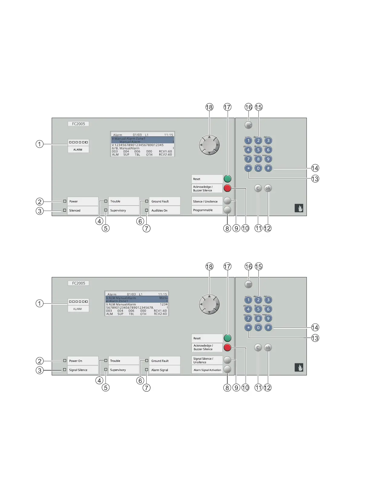
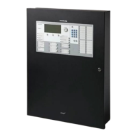
Home
Siemens
Control Panel
FC2005
Siemens FC2005 User Manual
4
of 1
of 1 rating
101 pages
Give review
Manual
Specs
To Next Page
To Next Page
To Previous Page
To Previous Page
Loading...
68
APPENDIX
-
G: L
CD
, CONTR
OLS AND
INDICA
T
ORS
The FC2005 has a buzzer
,
7 LEDs, 4 navigational push buttons, 4 push buttons, alphanumeric
keypad, 3 menu control buttons (menu, cancel
and
ok) and
a
communication port connector.
Panel in US
Panel in Canada
firealarmresources.com
72
74
Table of Contents
Table of Contents
2
Introduction
6
Control Panel Limitations
6
Preface
8
FCC Part 68 Warning
8
Industry Canada Statement
9
Service Requirements
9
Descriptions
10
Fc2005 System Description
10
Power Supply
11
Signaling Line Circuit (SLC)
11
Notification Appliance Circuits
11
Serial Interface Circuit (UFP)
11
Status Relays
11
Programming Port
11
Dact
11
Programmable Key
11
Optional Modules
11
City Tie Module (FCI2020-U1)
11
Battery Sets
12
Remote Printer Module (FCA2018-U1)
12
Auxiliary Modules
12
Serial LCD Annunciators
12
FT Series LED Driver/Annunciators
12
Battery Housing (FH2072-UA)
13
Universal Enclosure for Annunciators (FTH2073-UA)
13
Slc Addressable Devices
14
Smoke Detector
14
Heat Detectors
14
Addressable Modules (Monitor and Control)
14
Manual Stations
14
Sounder Base
14
Programming SLC Devices
15
Event History
16
General Design Features
17
Environmental
17
Power Limiting
17
Ground Fault Detection
17
NAC Operation
17
Security Features
17
Regulatory Standards
18
Underwriters Laboratories
18
Underwriters Laboratories of Canada
18
Federal Communications Commission
18
General Specifications
19
Environmental
19
Primary Power Supply (FP2011-U1)
19
Secondary Power Supply
19
Auxiliary Power Outputs
19
Status Relays
20
Notification Appliance Circuits
20
Serial Interface Circuit (UFP)
20
SLC Addressable Device Circuits
20
City Tie Circuits
21
DACT Circuits
22
Control Panel Operation
23
Operation Instructions
23
Standby Condition
23
Alarm Conditions
23
Trouble Conditions
24
Supervisory Conditions
24
Additional Operating Procedures
26
Lamp Test
26
History
26
Fc2005 Operating Instructions
27
Alarm Operation
27
Authorized Personnel Only
27
Trouble Operation
27
Event Scrolling
27
Fuse Replacement and Battery Maintenance
27
Fsd901 Operating Instructions
28
Alarm Operation
28
Authorized Personnel Only
28
Trouble Operation
28
Event Scrolling
28
Normal Standby Condition
28
Control Panel Installation
29
Parts Supplied - Fc2005
29
FC2005 Enclosure Package
29
FC2005 Main Board Package
29
FC2005 Configuration Kit Package
30
FC2005 Product Documentation
30
Control Panel Location
31
Installation
31
Enclosure Mounting
31
Remove Knock-Outs
34
Power Supply FP2011-U1 Mounting
35
Ground Wire Installation
36
Battery Installation
37
Optional City Tie Mounting
38
Main Board Assembly Installation
39
Earth Cable Installation
39
System Wiring
40
AC Connection
40
Battery Connection
40
Wiring
40
Control Panel Wiring Overview
41
Wiring Entering Enclosure
41
Install Wiring
41
Wiring Separation
42
Internal Structure
42
Power Supply and Battery Wiring
43
Status Relays
44
Auxiliary Power Outputs Wiring
44
NAC Wiring
46
Serial Interface Circuit (UFP)
47
Serial Remote Device Wiring Overview
49
SLC Addressable Device Circuit
50
SLC Addressable Device Wiring Diagrams
51
Optional City Tie/Leased Line
54
DACT Wiring
54
Programming the Control Panel
55
Keypad Programming
55
Pc Programming
55
Programming Security
55
Maintenance
56
General
56
Quick Test
57
Appendix-A: Reference Data
59
Wire Selection Guides
59
Resistance of Solid Copper Wire
59
Addressable Device Circuit Wire Selection Guide
59
Battery Size Calculations
60
System Current Draw Break down
60
SLC Current Draw Break down
61
Battery Size
62
Appendix-B: Compatible Devices
63
Devices for Addressable Device Circuits
63
UFP Devices
66
Appendix-C: Troubleshooting
67
General
67
System Events
68
Appendix-D: Alarm Verification
69
Appendix-E: Application Specific Detection
71
Appendix-F: Testing/Maintenance
72
Appendix-G: Lcd, Controls and Indicators
73
Panel in US
73
Panel in Canada
73
Communication Port Connector
74
LEDS, Buzzer and Dedicated Push Buttons
74
LCD Display
77
Appendix-H: Output Features
79
Output Activation- and Deactivation- Delays
79
Appendix-I: Pas / Pre-Signal
80
Pas
80
Pre-Signal
81
Appendix-J: Dact Information Overview
82
DACT Compatible Alarm Communicators
87
Wiring Diagram for Dsc's TL300CF and LE4010CF Connection, Including Trouble Reporting Route
88
LE4010-CF Configuration
89
TL300-CF Configuration
90
LE4010-CF & TL300-CF Power Supply Wiring Configuration
91
Appendix-K: Drift Compensation
92
Appendix-L: Releasing Operation
93
Appendix-M: Glossary
96
Appendix-N: Pad-4 Wiring Instruction
99
Other manuals for Siemens FC2005
Programming Manual
66 pages
Installation Instruction
12 pages
System Installation Instructions
24 pages
4
Based on 1 rating
Ask a question
Give review
Questions and Answers:
Need help?
Do you have a question about the Siemens FC2005 and is the answer not in the manual?
Ask a question
Siemens FC2005 Specifications
General
Brand
Siemens
Model
FC2005
Category
Control Panel
Language
English
Related product manuals
Siemens FC2025
144 pages
Siemens FC2050
144 pages
Siemens FC10
32 pages
Siemens FC924
144 pages
Siemens FC72x
62 pages
Siemens FC7xx
184 pages
Siemens FC901
66 pages
Siemens FC124-ZA
8 pages
Siemens FC901-U3
83 pages
Siemens FC726-ZA
10 pages
Siemens FC122-ZA
8 pages
Siemens FC901-R3
83 pages