Installation, connecting up, commissioning
3.3 Installing and connecting up the LINK
IE/PB LINK PN IO
36 Operating Instructions, 11/2017, C79000-G8976-C393-02
Installing and connecting up the LINK
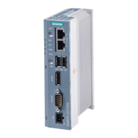
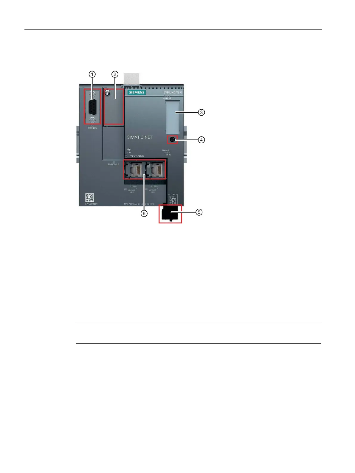
X2: PROFIBUS interface: 1 x 9-pin D-sub female connector
X3: Interface for ET 200SP bus adapter (behind the labeling plate)
X50: Receptacle for C-PLUG (behind the labeling plate);
Button. For information on the functions, refer to the section Interfaces, bus adapters, buttons
X80: Connector for the redundant power supply
X1: PROFINET interface, 2 x RJ-45 jacks with ring ports X1P1R / X1P2R
Figure 3-2 Connectors of the LINK
Installing and connecting up the LINK
Note
Only wire up the LINK with the power switched off.
Mount the LINK as follows:
1. Mount the LINK on the 35 mm DIN rail.
2. Connect the turned off power supply to the LINK. See section X80: External power supply
(Page 27).
3. Connect the LINK to Industrial Ethernet via one of the RJ-45 jacks (X1).
As an alternative you can use bus adapters at X3, that must be plugged in with the power
turned off. When using bus adapters, the Ethernet interface X1 is inactive.
 Loading...