EasyManuals Logo

Siemens IE/PB LINK PN IO User Manual

Siemens IE/PB LINK PN IO
92 pages
To Next Page IconTo Next Page
To Previous Page IconTo Previous Page
Page #79 background imageLoading...
Page #79 background image
Technical data
6.2 Pinout of the Ethernet interface
IE/PB LINK PN IO
Operating Instructions, 11/2017, C79000-G8976-C393-02
79
6.2
Pinout of the Ethernet interface
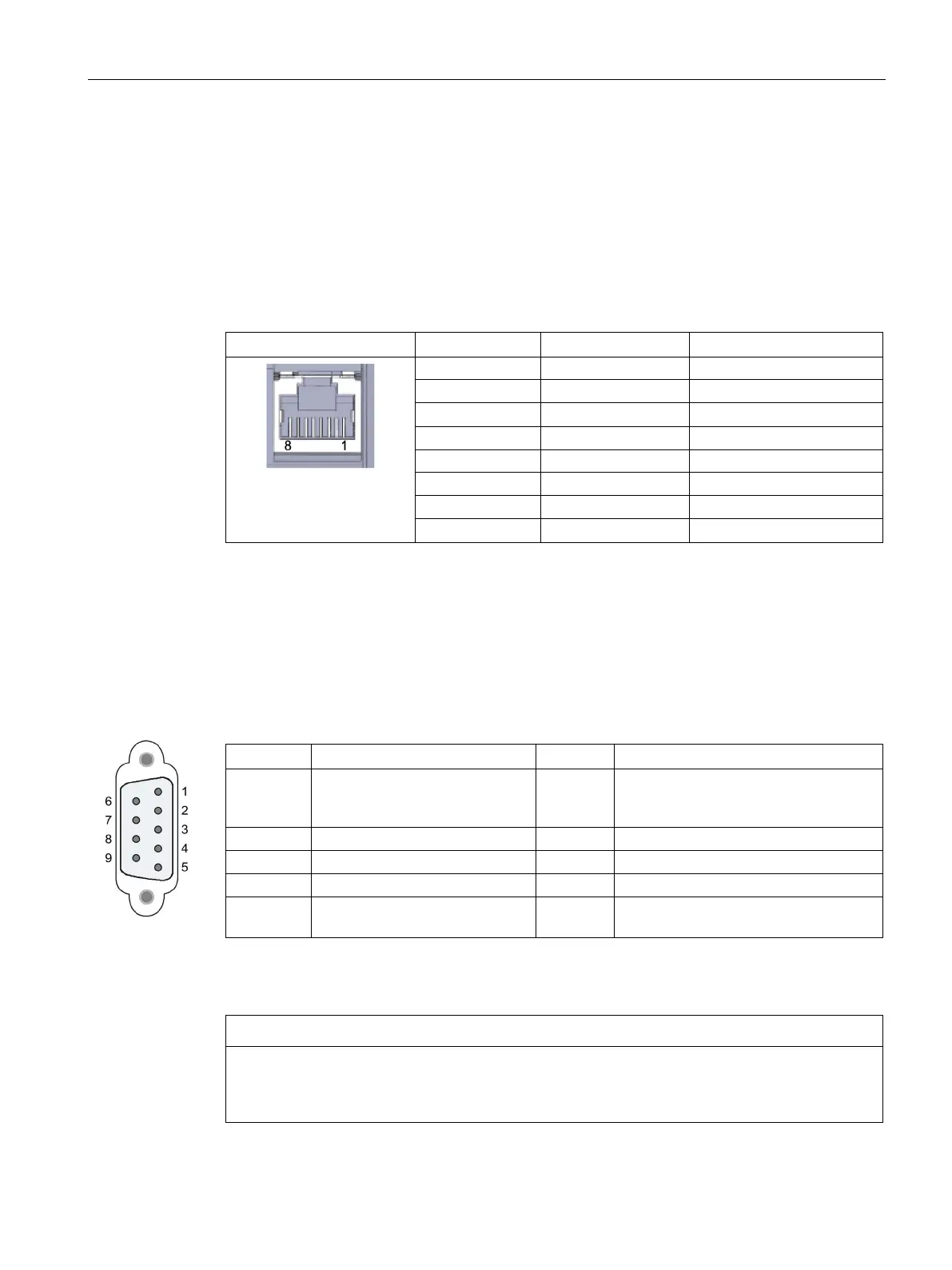
The table below shows the pin assignment of the Ethernet interface. The pin assignment
corresponds to the Ethernet standard 802.3-2005, 100BASE-TX version.
Table 6- 2 Pin assignment of the Ethernet interface
View of the RJ-45 jack
Pin
Signal name
Assignment
1
TD
Transmit data +
2
TD_N
Transmit data -
3
RD
Receive data +
4
GND
Ground
5
GND
Ground
6
RD_N
Receive data -
7
GND
Ground
8
GND
Ground
6.3
Pin assignment of the PROFIBUS interface
PROFIBUS interface
Table 6- 3 Pinout of the D-sub socket
Pin
Description
Pin
Description
1 - not used - 6 VP: Power supply +5 V only for bus
terminating resistors;
not for supplying external devices
2
- not used -
7
- not used -
3
RxD/TxD-P: Data line B
8
RxD/TxD-N: Data line A
4
CNTR-P: RTS
9
- not used -
5 DGND: Ground for data signals
and VP
Housing Ground connector
PROFIBUS cable and connector
NOTICE
Contacting the shield of the PROFIBUS cable
The shield of the PROFIBUS cable must be contacted. To do this, strip the insulation from
the end of the PROFIBUS cable and connect the shield to functional earth.

Table of Contents

Questions and Answers:

Question and Answer IconNeed help?

Do you have a question about the Siemens IE/PB LINK PN IO and is the answer not in the manual?

Siemens IE/PB LINK PN IO Specifications

General IconGeneral
BrandSiemens
ModelIE/PB LINK PN IO
CategoryGateway
LanguageEnglish

Related product manuals