EasyManuals Logo

Siemens Maxum II Reference Manual

Siemens Maxum II
100 pages
To Next Page IconTo Next Page
To Previous Page IconTo Previous Page
Page #52 background imageLoading...
Page #52 background image
8.
Remove 6 mounting screws from
the locations shown in the illustra‐
tion at right.
Mounting Screw Locations
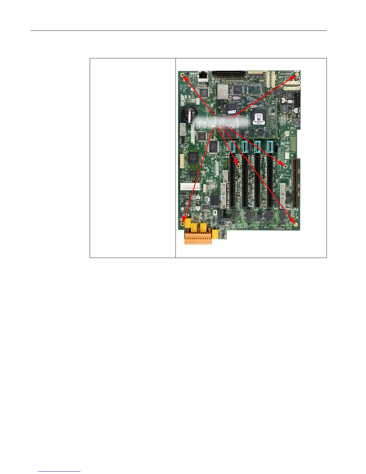
SIB3 Mounting Screw Locations
9. Remove the SIB, rear edge first to pull the I/O connectors from the SYSCON cage opening.
Installing a SIB3
1. Set the I/O mode switch on the SIB3 to the same position as the board that was removed.
2. Install a CAC3 using the procedure described earlier. The two boards together are called
the SYSCON2.1.
3. Install the SYSCON2.1 in the tray and secure with the 6 mounting screws removed earlier.
4. Install these cables to the SIB3:
I
2
C cables
Purge cable
Power cable
Serial cables
CAN bus cable if present
5. Install the ESB and reconnect the Ethernet cable from the rear RJ-45 connector to the
horizontal RJ-45 conncector on the CAC3.
Electronic Compartment Component Descriptions and Maintenance Procedures
2.3 System Controller Version 2.1 (SYSCON2.1)
Maxum II Reference Manual
52 Manual, 7/2017, 2000596-001

Table of Contents

Other manuals for Siemens Maxum II

Questions and Answers:

Question and Answer IconNeed help?

Do you have a question about the Siemens Maxum II and is the answer not in the manual?

Siemens Maxum II Specifications

General IconGeneral
CategoryGas Chromatograph
Measurement PrincipleGas Chromatography
Communication ProtocolsModbus, Ethernet, Profibus
Operating Temperature-20°C to 55°C
Power Supply24 VDC or 100-240 VAC
Mountingrack mount
ApplicationsRefinery, chemical, petrochemical, natural gas
DetectorsThermal Conductivity Detector (TCD), Flame Ionization Detector (FID)
Sample InletsMultiple
DimensionsVaries by configuration (e.g., 19" rack mount)

Related product manuals